Testing an engine on an engine dynamometer can be a stressful task for not only the dyno itself, but also the dyno operator and even the customer. Quite a lot of work goes into connecting an engine to a dyno, and an improper set up can greatly influence the accuracy of the engine dyno readings and even the longevity of the testing components.
Since 1972, SuperFlow has been producing driveline test equipment for performance engine builders, race teams, universities, and technical schools around the world, and even the U.S. Military. In the video above, SuperFlow’s own Mike Giles walks viewers through the process of mounting an engine to the Powermark and Black Widow driveshaft-driven engine dynamometers; along with an overview of the various components and accessories crucial to getting an accurate reading.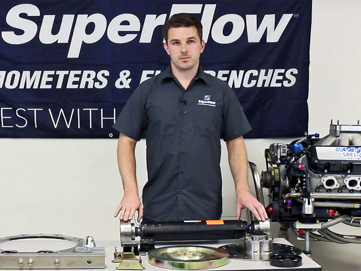
Watching this video will give you a far better understanding of engine dynamometers in general; and give you a better idea of what your operator is actually doing the next time you and your project pay the dyno cell a visit.
If you’ve never taken your engine to a dyno facility before and are uneasy about how to prepare, check out our previous article on visiting a dyno cell for the first time!
Vibration And How To Combat It
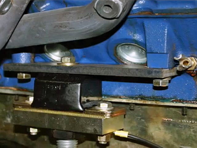
One of the most important aspects when it comes to receiving a clear and accurate signal at the engine dyno is dampening the natural vibrations produced by the engine before they can be picked up by the load cell and produce a faulty torque signal — throwing off the power figures.
For rear engine vibration isolation, SuperFlow utilizes various polyurethane engine and transmission mounts from Energy Suspension that sit between the engine mount and the cart. For the front of the engine, another set of Energy Suspension’s transmission mounts are used, either independently or in conjunction with conical adapters and mounting plates.
For vibrations emitted directly from the crankshaft, a torsionally compliant driveshaft is used. This driveshaft is designed using a smaller inner tube and wider outer tube, which are then isolated from one another using a specific durometer of rubber. This rubber acts as a barrier to prevent the crankshaft vibrations picked up by the inner tube (engine side) from transmitting into the outer tube (dyno side).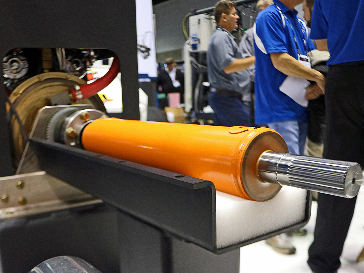
Additionally, you’ll notice that the driveshaft utilizes CV joints (constant-velocity joints) instead of your usual U-joint (universal joint). While U-joints might be cheaper, as the driveshaft rotates and the U-joint rolls over it creates an artificial spike in the torque signal twice per engine cycle. Ultimately, CV joints provide a smooth power transfer from the crankshaft to the load cell with a reliable and clean torque signal.
From The Cart To The Dynamometer
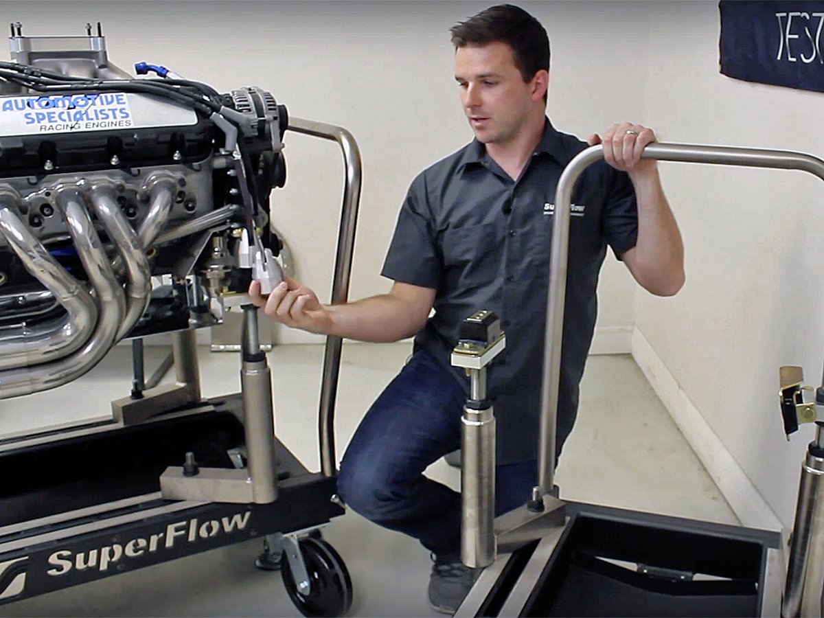
Once the engine has been secured to the cart, you can finally begin the process of mating the engine to the driveshaft and aligning the cart with the load cell.
It’s important to pay attention to exactly how far the splined portion of the driveshaft is inserted into the engine. Too far and the splined shaft will sit against the flywheel, putting extra stress on the driveshaft, not far enough and the splines won’t be fully engaged which may damage the driveshaft splines, the CV joint or even the engine.
Because CV joints are being used as opposed to U-joints, it’s important to verify that the driveshaft has just a slight amount of misalignment at each end. This will increase the CV joints’ longevity by allowing the grease within the joint to be more easily dispersed throughout the joint internals as it rotates.
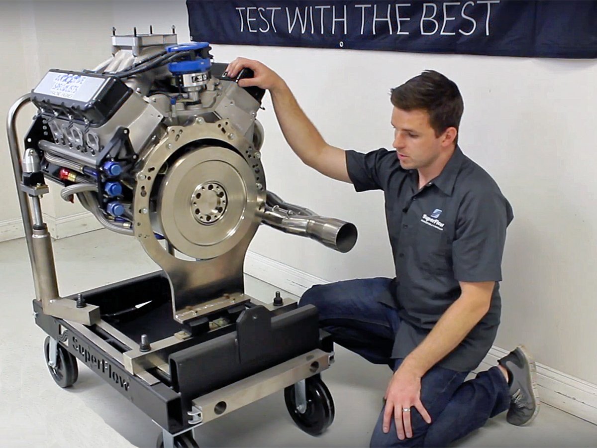
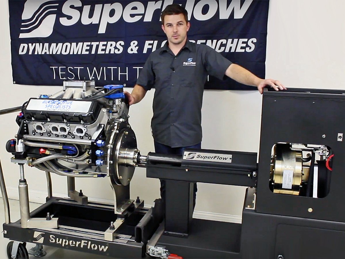
An engine mounted to the docking cart and ready to be connected to the engine dyno (left), and the engine mounted to the dyno and ready to make some noise.
For a closer look at SuperFlow’s entire product line, including Powermark and Black Widow engine dyno, be sure to check out the company’s website — and prepare to be amazed…