Long gone are the days of simple engine systems, with mechanical controls and settings altered through the loosening and tightening of bolts. Now, regardless of how you feel about it, engine control units monitor and control every single aspect of the engine’s performance through various engine sensors, in order to fine-tune everything on the fly.
Once you’ve accepted that you are powerless over the advancement of technology, the next step is to thoroughly understand what all is being monitored and accounted for in your engine’s programming. While it might vary slightly based on make, model, and model year, all OBD-II engines will utilize some of the listed sensors, and chances are, the newer the engine, the more of the listed sensors it will use. Whether your engine(s) use all of the listed sensors or not, it never hurts to understand all of the potential sensors in the system.
The video above covers 16 sensors with an in-depth description of each sensor, how it works, its failure mode, and the symptoms of a sensor failure. We won’t be going into that much detail in this article, so be sure to watch the video for all of the information.
Position Sensors
Pretty self-explanatory, position sensors monitor the exact position of your crankshaft, camshaft, and throttle position. They basically translate their mechanical movement into an electronic signal for the ECU to reference. Crank position sensors replace the need for manually setting timing with a strobe light and believe it or not, the distributor gear’s interface was essentially an analog camshaft position sensor.
Now, instead of a mechanical interface, both the cam and crank position sensor assemblies use a reluctor wheel and either a Hall-effect or variable-reluctance sensor. The missing tooth on the reluctor wheel provides a reference point for each rotation, and then each individual tooth provides a signal to the computer to not only locate the shaft (either crank or cam) in its rotation, but also to accurately measure its speed, and whether it’s accelerating or decelerating.

The MSD crank trigger kit is an early form of a crankshaft position sensor. While it only has four trigger magnets, that’s all it needs for its intended application. Modern OEM reluctor wheels — like on the LS — have 24 or 58 teeth, and provide detailed crankshaft location information to the ECU, especially in conjunction with a camshaft position sensor.
The throttle position sensor is slightly different in that it determines the throttle blade(s) position through a variable resistance assembly, which changes the sensor’s output voltage based on where in the throttle blade’s 90-degree rotation is it. This allows the ECU to accurately measure throttle position and control variables such as spark timing and fuel based on throttle position.
Airflow Sensors
Whether your engine is a “MAF” or “MAP” style engine, the simple fact is that both are ways to measure (or calculate) how much air is flowing into the engine, so that the ECU knows how much fuel to inject for the desired air-fuel ratio.
Both the mass airflow meter and the vane airflow meter use a physical measurement of airflow to determine the amount of air the system is ingesting, while a Manifold Absolute Pressure sensor system uses manifold pressure and air temperature to calculate the amount of air in the system. So while the MAP sensor is not actually an airflow sensor, it is critical in the calculation of airflow, and is an effective method.
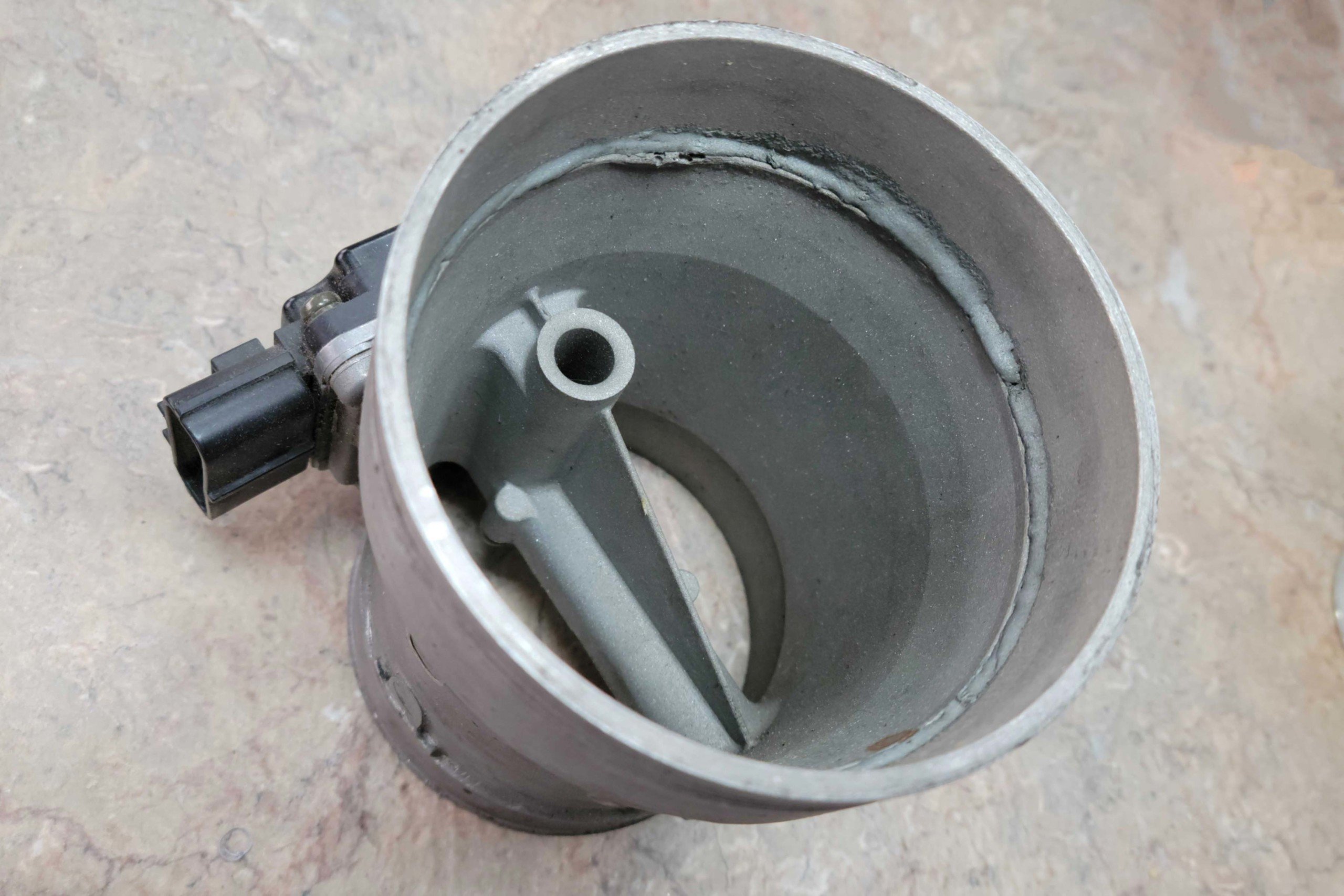
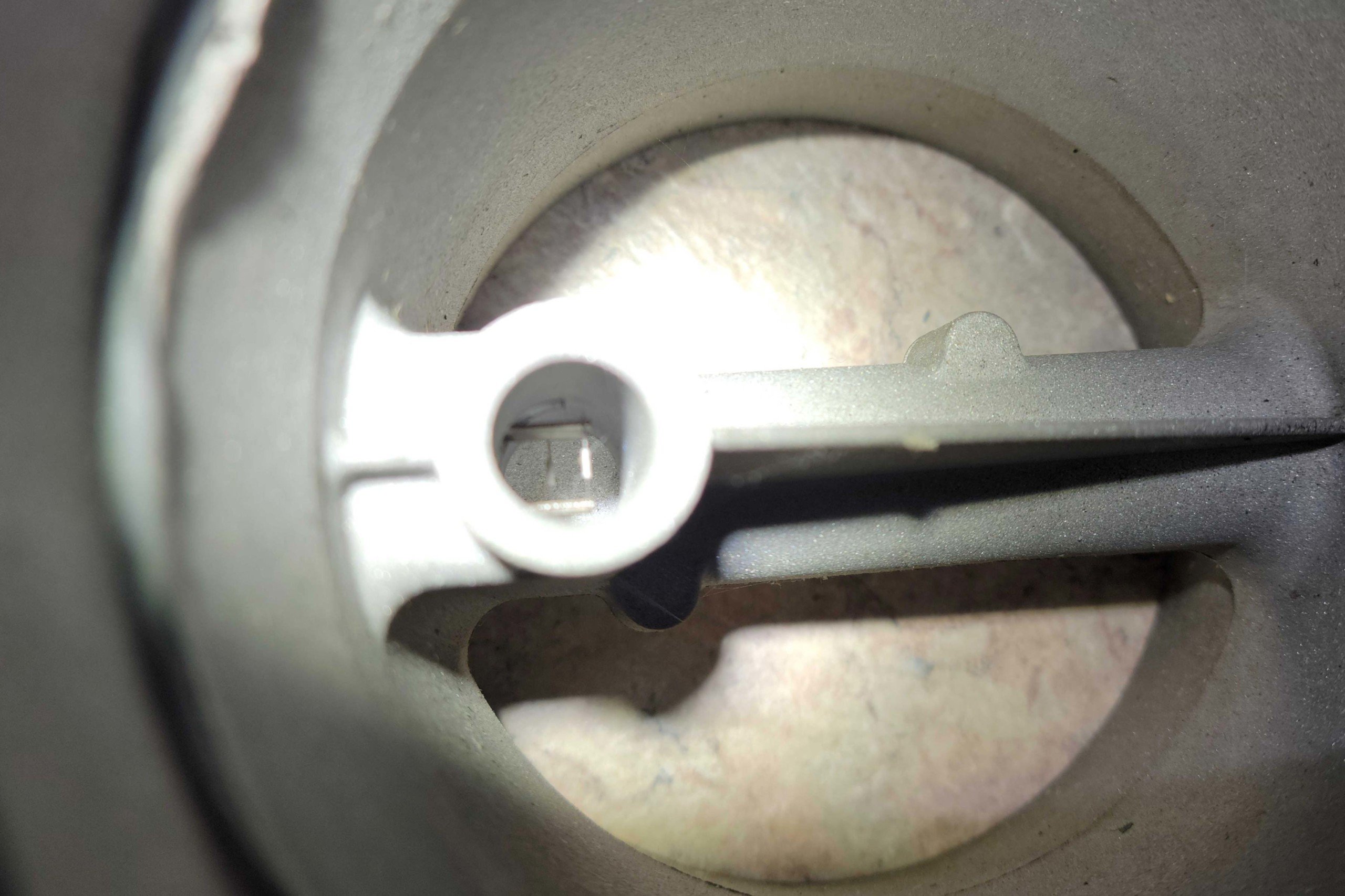
The mass airflow sensor physically measures a calibrated amount of air via the wire in the small circular passage. By knowing the size of that oriface, and the overall size of the sensor's opening, it can calculate the exact amount of air being ingested by the engine.
In a mass airflow sensor, there is a heated substrate — either a wire or film — contained within a orifice of a calibrated size, which measures the physical amount of air passing over the sensor. With that data, it extrapolates how much air is flowing through the entire sensor housing.
The vane-type airflow sensor uses a flap, whose position is monitored by a sensor similar to a throttle position sensor. As airflow increases, the air presses against the vane, which is under pressure from a calibrated spring. As airflow increases, the vane opens a certain amount, and the ECU knows how much air is moving into the systems.
Pressure Sensors
As the name implies, pressure sensors accurately monitor the pressure of a fluid (remember, air is a fluid) for use by the ECU. Generally, the sensor’s range is sized closely to the expected operating range of the system, in order to provide the most usable resolution possible. Jumping back to the manifold absolute pressure sensor, that is why you’ll see the sensors described as one-bar, two-bar, and so on.
The number of “bars” describes the sensor’s available range in the unit of pressure called bar (which equals 14.5 psi). So a one-bar sensor would measure from 0-14.5psi so would only be usable in a naturally aspirated application. A two-bar sensor would accommodate up to 14psi of boost, and so on.
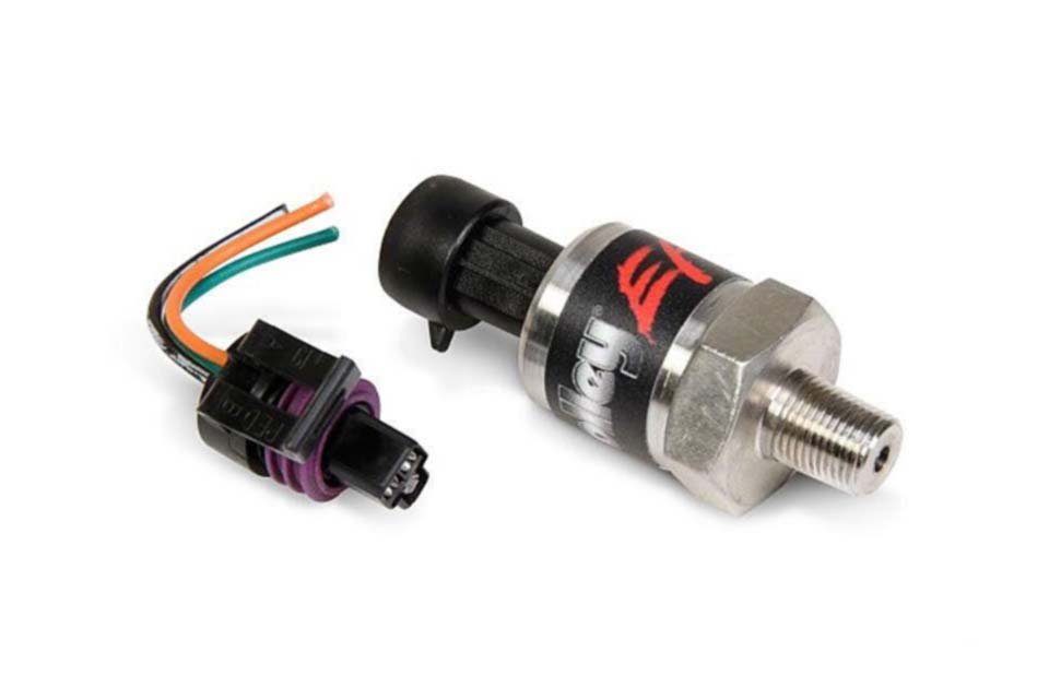
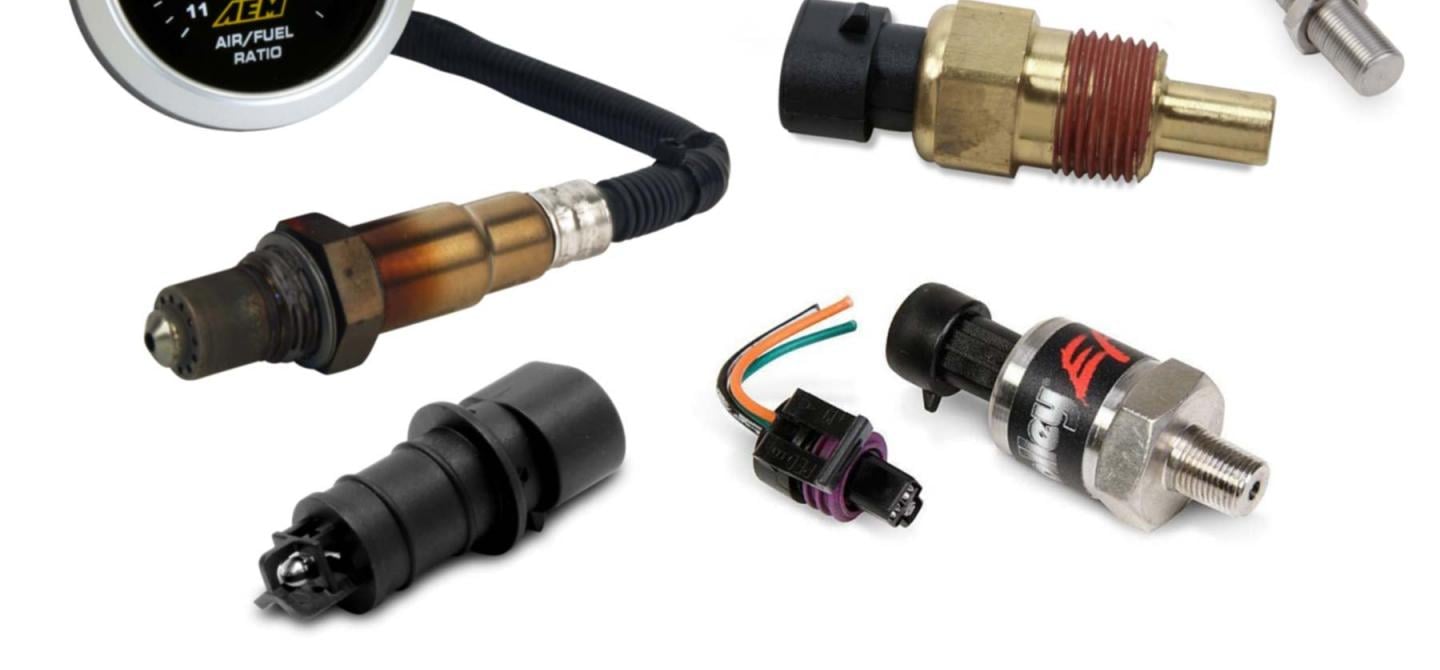
Pressure sensors are all relatively similar in their construction and outward appearance within a given product line, like this Holley EFI 0-100psi pressure sensor. Where the sensors really differ is their measurement range. Using a 0-200psi sensor in an application that won’t see more than 100psi would leave half of the sensor’s resolution unused. Using a 100psi sensor would effectively double the resolution delivered to the ECU.
Obviously, an oil pressure sensor is designed to make sure that you have oil pressure in your engine, but in today’s modern engines, variable oil pumps exist, so being able to accurately determine the exact pressure of the system is important since the ECU will tailor the pump’s output to the current conditions the engine is experiencing.
A fuel pressure sensor works in exactly the same manner, both as a single-pressure “on/off” switch (also called a Hobbs switch) and as a highly precise pressure measurement sensor. By knowing the pressure of the fuel, the ECU knows how long to open the fuel injector (the injector pulse-width) to achieve the desired air-fuel ratio.
Temperature Sensors
Again, the name kind of explains what’s being measured when it comes to temperature sensors. Starting with the intake air temperature sensor, the IAT sensor is a key part in determining the density of the incoming air, which plays a large part in the proper amount of fuel required.
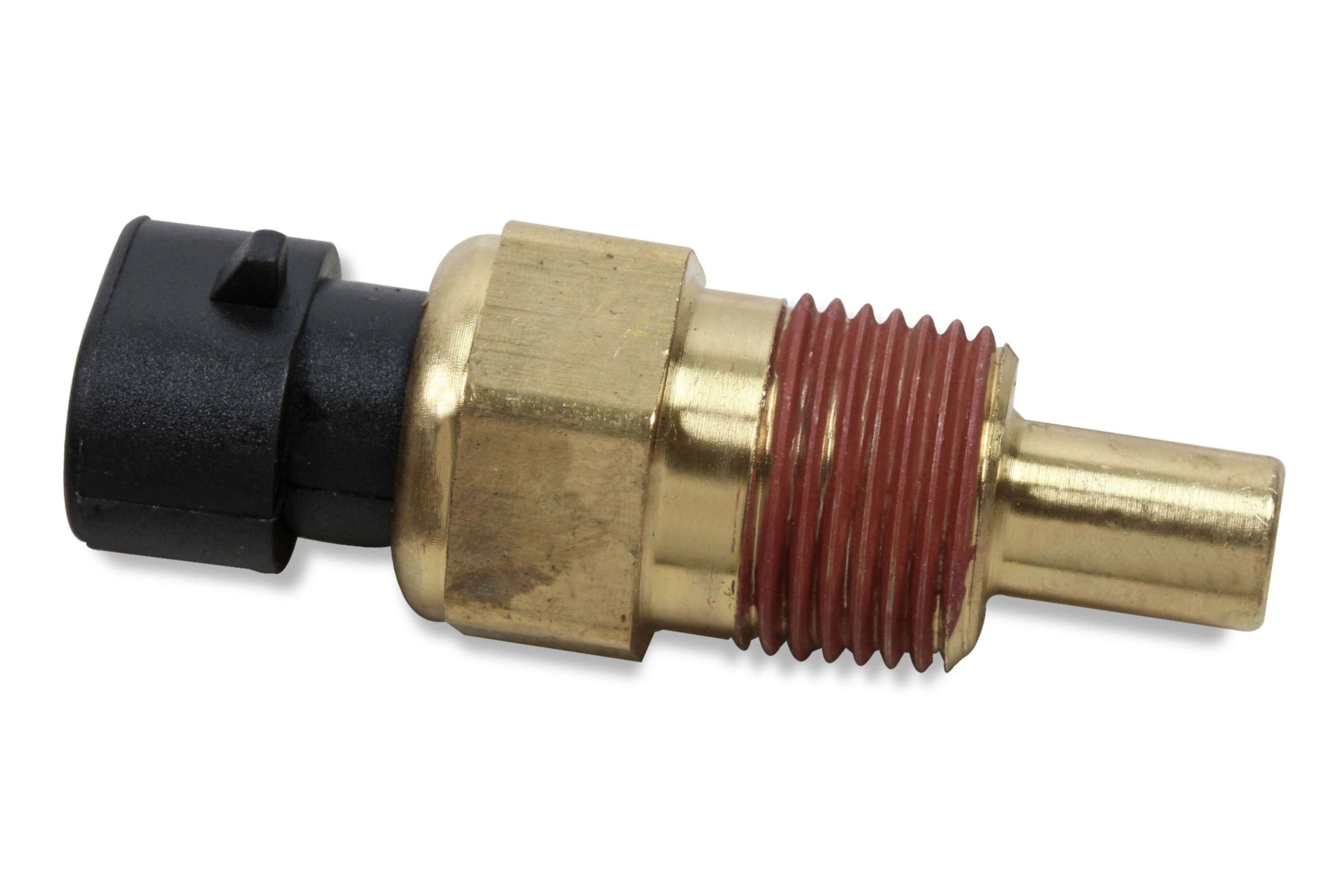
The coolant temperature sensor and oil temperature sensor are similar sensors, as they both measure fluids in a similar temperature range. Both of these sensors are critical to an ECU, as oil and coolant temperatures indicate overall engine temperature, and can tell the ECU to reduce the performance of the engine in order to prevent damage in the case of rising temperatures, as well as reducing emissions before the engine has gotten up to operating temperatures.
Both of these are temperature sensors from Holley. On the left, the brass sensor is designed to measure the temperature of fluids (like oil and water) with a range commensurate to that of the fluids being measured. On the right, the intake air temperature sensor is built specifcally to measure air temperature.
Fuel temperature sensors are relatively new in the overall equation, but as extreme measures are being implemented to increase efficiencies (and reduce emissions) the temperature of the fuel has been incorporated as a way to determine its density, and further refine the ability to control air-fuel ratios to more places to the right of the decimal.
Emissions Sensors
Now, before you immediately dismiss the emissions sensors, understand that of the four sensors in this category, three are used in the performance world. Possibly the most common emissions sensor used these days is an oxygen (or O2) sensor.
Available in narrowband and now wideband versions, the oxygen sensors measure the amount of oxygen present in the exhaust gasses, which in turn tells the ECU the actual air-fuel ratio. Wideband oxygen sensors have become one of the biggest game-changers — both in OEMs and in aftermarket performance — by allowing ECUs access to accurate real-time air-fuel ratio measurements.
Next is the exhaust gas temperature (EGT) sensor. These are typically used to measure the exhaust temperature of a diesel engine’s exhaust, and the changes in that temperature can indicate the air-fuel ratio, and were often used for tuning prior to the widespread availability of wideband oxygen sensors. EGT probes are more commonly found these days in OEM diesel applications and occasionally in OEM turbocharged gasoline engines.

While wideband oxygen sensors originally came about as an emissions-reduction tool, they have become an indispensable tool in the world of performance tuning.
Modern diesel engines can also have a Nitrogen Oxide (NOx) sensor which, like an oxygen sensor, measures the amount of nitrogen oxides in the exhaust. Unlike the oxygen sensor, however, this is solely to monitor the performance of active emissions systems and control the injection of Diesel Exhaust Fluid.
Finally, we have the often-underappreciated knock sensor. This sensor can detect engine knock in real-time and allow the ECU to correct the condition causing knock, usually by pulling timing. While some will call it a tuning bandaid, knock sensors have probably saved more performance engines from engine-killing detonation than we’ll ever know. And in the OEM role, they can prevent a bad tank of gasoline from causing serious damage.
As engine sensors advance, not only will the ECU get better data upon which to make its decisions, but ECU’s capabilities and responsibilities will expand as well, in order to control engines to a level we previously thought impossible.


