
 Building an efficient drag-race engine around boost requires a little more math and planning than one might expect. To start, the engine builder may have to work within boundries established by the rulebook. But the primary goal is to match the boost potential of the power adder — whether that’s a supercharger or turbocharger — to the engine.
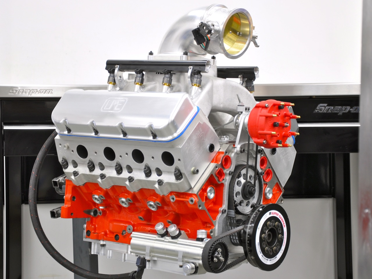
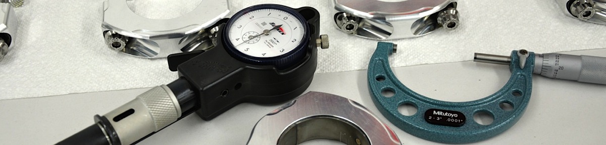
Ready for installation into the Blown Z racecar, the 400ci LSX engine built by LME will soon be fitted with a CDS gear drive and ProCharger F-1X supercharger.
When the team behind the Power Automedia project vehicle known as BlownZ mapped out an off-season rebuild agenda for both the chassis and powertrain, one primary goal was stepping up to a new ProCharger F1XR supercharger. Last year with driver James Lawrence, Blown Z won the NMCA West World Finals in 275 Drag Radial and finished third in the 2013 points chase. That engine was a 388ci LSX mated to a ProCharger F1X. Plans for the 2014 season call for improving on the team’s personal best run of 7.353 @ 190 mph and posing a consistent threat in NCMA Street Outlaw, PSCA Wild Street and WCHRA 275.
To that end over the winter break, Blown Z was treated to a stiffer chassis and roll cage, redesigned suspension and tranny upgrade (‘glide to a TH400). Late Model Engines (LME) of Houston, Texas, was also recruited to assemble a new LSX-based engine to complement the more potent F1XR.
“A big part of this build is maximizing the engine rpm level with that blower,” explains LME’s Bryan Neelen. “That was the point of building a 400-cubic-inch engine as opposed to a 427 or bigger. Each turbo or supercharger has efficiency range based on size of its turbine wheel. We worked to get this new supercharger in its peak efficiency at 9,500 to 9,700 rpm.”

Short-block Components
- Cylinder block: Chevy Performance LSX (PN 19260095)
- Machining and assembly: Late Model Engines
- Crankshaft: Callies billet
- Balancing: Late Model Engines
- Connecting rods: GRP Pro Series, 6.050 long w/ 1.0 width at pin
- Pistons: Diamond 4.125 bore w/ 1.255 compression height and 15.6cc dish
- Piston pins: Trend, .927 x 2.500 and .210 wall.
- Piston rings: Total Seal, .043, .043, 2mm
- Bearings: Clevite (PN CB663 HND – rod, MS2199 H – mains)
- Camshaft: Comp Cams custom grind
- Lifters: Jesel .927 keyway (PN 53451C)
- Belt drive: Jesel (PN KBD 31610)
- Fasteners: ARP
- Oil pan: Dailey Engineering billet pan
- Oil pump: Dailey Engineering 6-stage
- Damper: ATI
- Head gasket: Cometic custom, .063 thick
This action plan stems from the premise that an internal combustion engine — in its most simplistic form — is an air pump. Filling the cylinders with all the available air-fuel mixture will result in the most efficient engine. Remember when NASCAR mandated restrictor plates for superspeedways? At the time, the reduced air charge cut horsepower in the 358 cubic-inch V8 engines from around 750 to 450. But some savvy engine builders lowered the displacement to around 300 to 320 ci and picked up horsepower with smaller engines! They were just matching the engine size to the available airflow and optimizing the engine’s efficiency. Such is the strategy LME assumed in determining Blown Z’s engine parameters.
“Instead of building a bigger engine and running out of air sooner, we go with a smaller engine that will allow more rpm,” says Neelen. “The goal of this engine was to turn more rpm than others in the class. When you’re turbo or supercharger limited, you adjust the displacement to help turn the rpm and still make power.”
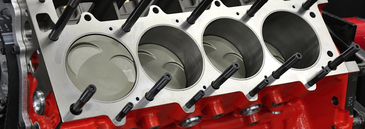
Once all the decisions were finalized and parts ordered, the majority of build time focused on machine work and pre-assembly fitting and measuring. The cast-iron Chevy Performance LSX cylinder block secured from Pace Performance comes with numerous features to support high-boost and high-horsepower applications, but considerable work is still needed for optimum durability and sealing.
“The order of operations is so important,” stresses Neelen. “We do as much as we can to truly blueprint the block.”
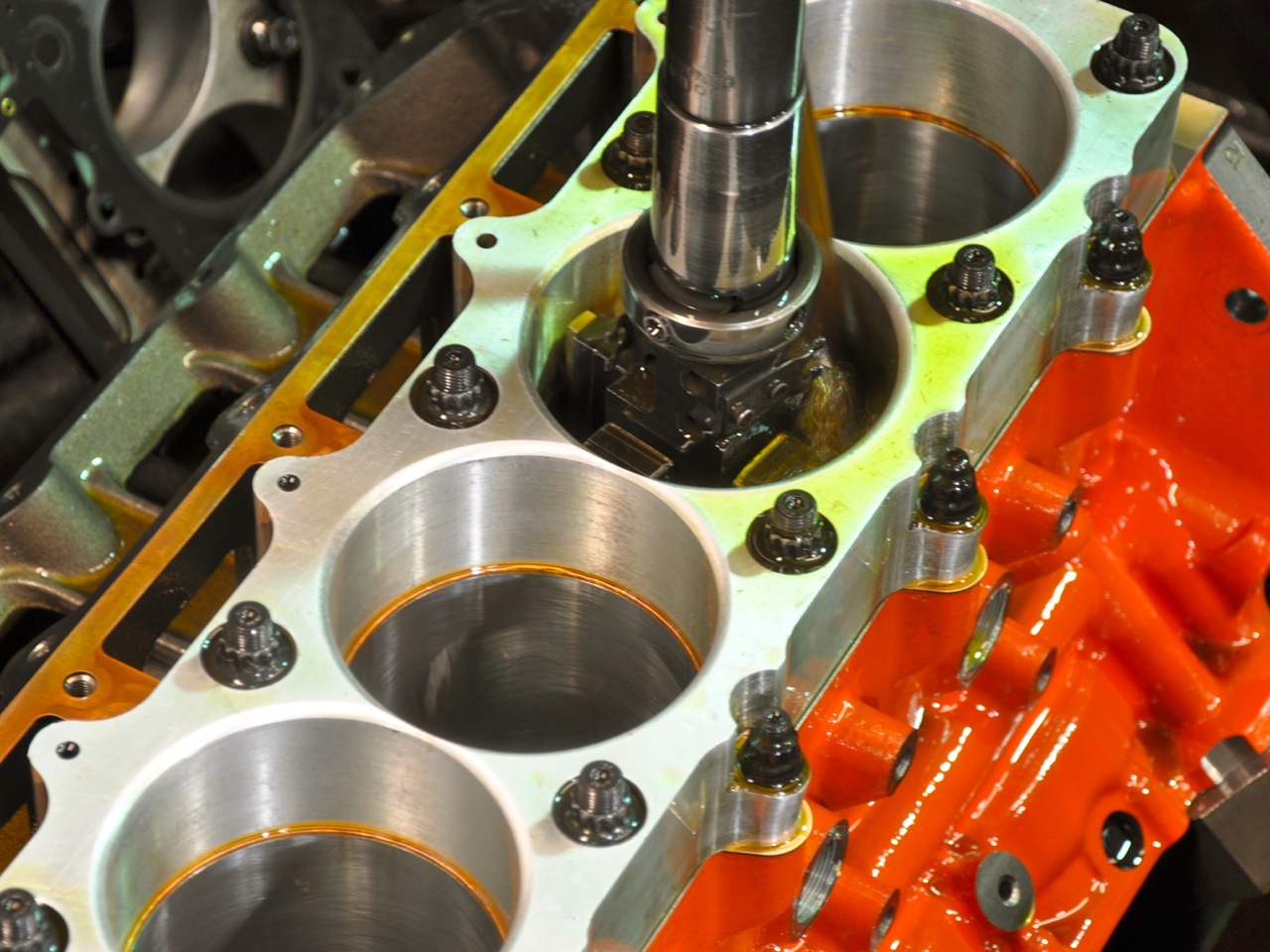
The block is first align-honed to establish the centerline of main bearings. Based on that centerline, an outside shop enlarged the cam-bearing bores to support a 60mm cam core. From there, LME secured the block into a CNC machine.
Left: After an outside shop enlarged the cam-bearing bores to accept a 60mm cam core, LME strengthened the LSX block by machining the open-deck water jackets to accept 1/2-inch-deep steel plugs. Middle: After the plugs were pressed in place, water holes were drilled and the O-ring grooves were machined. Right: Next, the main bolt holes were drilled and tapped for 1/2-inch studs. Left two photos: LME also machined the lifter bores to accept bronze keyway bushings. Right two photos: The block’s front face needed some machining to receive the Jesel belt drive.


Cylinder Heads & Induction
- Cylinder heads: Edelbrock LS-R
- CNC machining & port design: Race Flow Development
- Valves: Ferrea, 2.250 titanium intake, 1.600 Super Alloy exhaust
- Valve springs: PAC (PN 1357)
- Valve retainers: PAC (R509), titanium
- Shaft rockers: Jesel, 1.9:1 ratio
- Pushrods: Manton custom, 9.590 intake, 9.785 exhaust, single taper 9/16 w/ .188 wall
- Valve covers: Granatelli custom billet
- Intake manifold: Wilson custom
- Throttle body: Wilson 123mm
- Fuel injectors: Billet Atomizers, 225-pound
- Engine management: Holley Dominator
- Distributor: MSD
- Distributor drive: Jesel belt drive
Starting point for all block work
“We go off the cam and crank centerlines for all the additional machining,” adds Neelen, “so we know we’re making the block truly perpendicular to the mains.”
Since the block is designed around 4.400-inch bore centers, much of the machining is programmed with that specific data point.
“So, you punch that first hole, and then move 4.400 inches and so on,” explains Neelen. “Even when clearancing for the stroke, you find the centerline of the Number 1 cylinder, clear the opposite side, then move over 4.400 inches. On the other side you backtrack the width of the connecting rod. All the clearance marks will be in the exact spot. There’s no guess work.”
For racing purposes, the most critical machine work focused on strengthening the deck. LME machined out a uniform pocket in the water jackets to accept 1/2-inch deep plugs that were pressed in placed to add rigidity to the surface area. Water holes matching the gasket and cylinder head were then drilled as needed.
“When we started getting into high-horsepower applications with the LS, we would see cylinder wall distortion, particularly around the bolt holes,” explains Neelen. “You would see little black shadows close to those holes where the ring was not riding on the cylinder. And this was especially prevalent on the LS where the water jackets are wide open.”
The O-rings, Cometic copper head gaskets and torque plates were tightened according to specs before the cylinders were finished honed to 4.125-inch bore.


Left: The Callies Ultra billet crankshaft features center counterweights and double keyways. It also received a full Aero-Shed finish to help repel oil droplets and reduce internal drag. Right: In expectation of the engine approaching 10,000 rpm, LME dialed in a 2-percent overbalance to the rotating assembly
Benefits of stiffening the deck
The original purpose of closing up the water jackets was to prevent combustion pressure from leaking into the coolant passages in certain high-boost situations. By closing up the water jackets and moving the coolant holes away from the cylinder, there was less chance of pressurizing the coolant system.
“Then we discovered a side benefit when we noticed that cylinder wall shadowing went away,” adds Neelen. “Even with a 3,000 horsepower engine, we had little to no cylinder-wall distortion. Less cylinder-wall distortion equals better ring seal, which equals better power.”


Also comprising the rotating assembly are GRP aluminum rods, Diamond custom pistons, Trend heavy-wall wrist pins, Total Seal rings and Clevite bearings. The hard-annodized pistons feature lateral gas ports and an anti-friction coating. Note that rod bearings included standard and -1 so that LME could mix or match to achieve the proper clearance, if needed.

LME measured and double-checked every crucial tolerance and clearance in the engine. Steps shown here are measuring the stretch on the ARP L19 bolts and checking the wrist-pin clearance.
This machining process is much more effective than the traditional filling of the block with cement or some other type of filler. Those treatments only strengthened the bottom of the cylinder.
“Ninety percent of power is made in the first inch of piston travel,” says Neelen. “By strengthening the top of the block, that’s where you will see the gains.”
It should hit 9,500 with boost at the track and pick up 1,000 horsepower with the blower.–Bryan Neelen, LME

LME also machined the lifter bores accept Jesel keyway lifters. Final block preparations include milling the deck to the correct height, drilling and tapping for the head studs, O-ringing the cylinders for a .055-inch wire, blocking certain oil passages to ensure priority main oiling and machining the face to accept a Jesel belt drive. The cylinders are torque-plate honed to a 4.125-inch bore with the Cometic copper head gasket and the welded stainless-steel O-rings in place to help “tone” the block properly. LME then uses a profilometer to check the cylinder finish.
Striving for perfect finish
“We have specific Ra, Rv and Rp values we shoot for in each application,” says Neelen. “We know what works best for us.”
LME’s next big chore was balancing the rotating assembly. Each component was weighed to ensure equal mass across the cylinders, then each end of the connecting rods was weighed so that LME knew how both the rotating and reciprocating components were acting on the crankshaft. An extra five grams was added to each bob weight to compensate for oil drops, then the crank was balanced to 1/4-ounce tolerance.


From left: Once the block was prepped, LME started the short-block assembly. The crank and cam were installed followed by the piston-rod assemblies. Necessary clearances were double-checked, such as the rod bolts to the block. In another step the oil galley on the pan rail was blocked as LME went with priority main oiling.
“We also overbalanced by two percent. We typically do that for engines that will be seeing 10,000 rpm,” says Neelen.
The foundation for the rotating assembly is a Callies Ultra Billet 3.75-inch crankshaft. It features Ultra-Shed counterweight profiles that move oil in a precise direction to avoid hitting the rod journals or counterweights, and the Aero-Shed surface finish eliminates stress risers and improve aerodynamic efficiency inside the crankcase. The Ultra Billet crank is machined from low carbon, high nickel EN30B steel that receives multiple heat treatments.
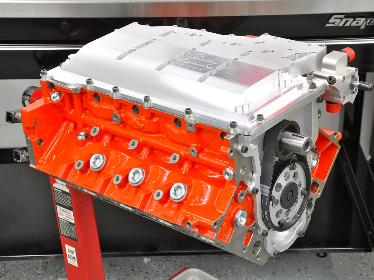
The Dailey Engineering dry-sump system was custom made for the engine, starting with a billet oil pan.


From left: The system includes 6-stage pump driven by a HTD belt. Note the LME spacer needed between cam drive and the gear on the ATI damper.
Swinging on the Callies’ arms are GRP Pro Series 6.050-inch aluminum rods and Diamond forged 2618 alloy pistons that produced an undisclosed compression ratio. The rods are secured with ARP L19 bolts while pistons feature lateral gas ports and double pin oiling. The pistons also received the Double Diamond Coating, which is a combination hard anodizing overall and an additional anti-friction moly coating for the skirts. Holding the pistons to the rods are Trend Performance .927-inch x 2.500 DLC-coated .210-inch-wall wrist pins that are secured with wire locks.
Short-block assembly
Crucial to sealing the cylinder in a boosted application is the piston ring package. The Blown Z team custom-ordered the pistons to accept Total Seal’s M2 tool steel .043 top ring that features a uniform barrel face profile. Rounding out the ring package are a .043 Napier stainless-steel second and 2mm oil rings. Another feature of the Total Seal top two rings in a patented lapping process, not traditional grinding, that ensures a very precise axial tolerance of .00015 inch. That means these rings boast an extremely uniform thickness for a tight and consistent fit into the ring groove.
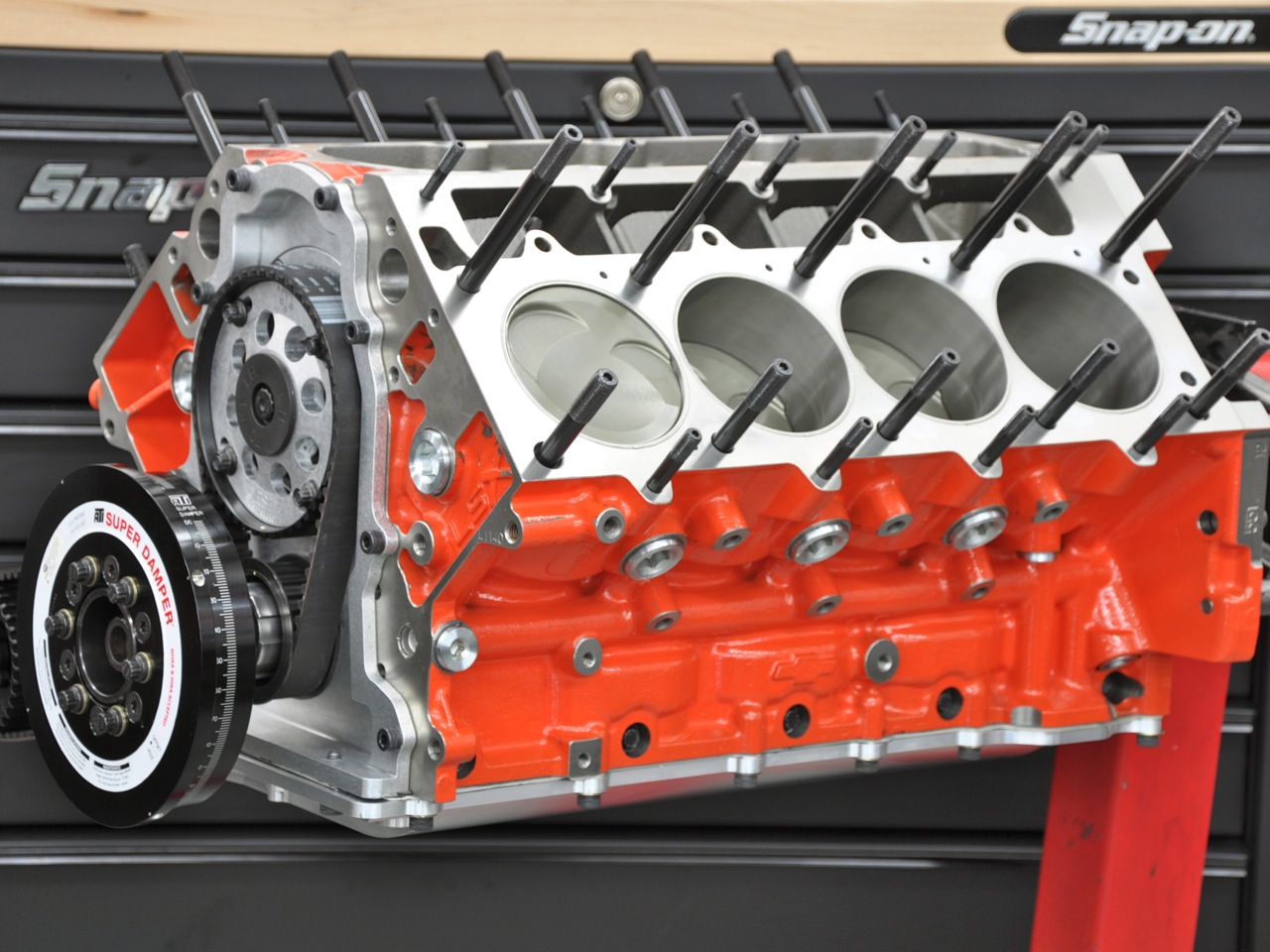
An ATI damper — already fitted with a gear to support the HTD belt for the oil pump — is installed along with the ARP 2000 head studs (1/2-inch primary, 3/8-inch outer and 8mm inner).
The short block was pre assembled to check clearances, including piston-to-valve and cam end play. The latter was necessary as LME swapped out the bronze bushing that comes with the Jesel cam-gear hub for a Torrington bearing. That required some machining, so the final play with the custom dual-pattern Comp Cams billet camshaft in place was double checked.

Specifications
- Bore x stroke: 4.125 x 3.75
- Displacement: 400 ci
- Main torque: 60 ft-lb, 25 ft-lb sides
- Rod torque: .006-inch stretch
- Head torque: 120 ft-lb
- Main bearing clearance: .003-inch
- Rod bearing clearance: .0025-inch
- Piston-to-wall clearance: .006-inch
- Valve spring pressure: 375 lb, seat; 1,116 lb open
- Camshaft duration @ .050: undisclosed dual pattern
- Lobe centers: undisclosed
- Lift at valve: .900-inch
When satisfied that all tolerances and clearances were up to spec, LME lubricated the parts as needed for final short-block assembly, which included installation of the Dailey Engineering “Signature Series” billet dry-sump oil system. The Dailey 6-stage pump is integrated into a beautifully machined billet pan designed with separate crankcase compartments that correspond with each pair of opposing cylinders. All of the scavenge sections are a 2-lobe, Root’s style configuration. The front section is the engine oil pump and measures 1.45 inches wide, utilizing a spur-gear design and provides pressure to lubricate the engine. The next four scavenge stages measure 1.250 inches wide and pull oil and vacuum from the crankcase. These four stages are channeled directly into pan’s separate compartments, each of which has a debris screen. The fifth stage measures 1.7 inches wide and is used to assist in making crankcase vacuum. This section is independant of the oil pan and can pull vacuum from the top of the block or where needed to scavenge oil. The pump is set to rotate about 80-100 percent of crank speed and can pull up to 18 inches hg of vacuum at full engine speed with power levels up to 2,000 horsepower.
EngineLabs covered the cylinder heads and intake manifold development in great detail in a previous story. To recap, Curtis Boggs at Race Flow Development started with a set of a Edelbrock Victor Pro Port LSR heads and reshaped the ports and combustion chambers on the CNC machine. The heads were then fitted with 2.250-inch Ferrea titanium intake valves and 1.600-inch Super Alloy exhaust valves. With final lift approaching a full inch, keeping the those valves stable is the job of PAC Racing 1300 Series valve springs. This dual spring assembly (1.500-inch diameter outer spring, 1.050-inch diameter inner spring) provides an installed load of 350 pounds and 1,116 pounds open. These springs are constructed from a proprietary Kobe steel blend and come with chamfers on the inside diameter to facilitate retainer clearance and reduce stress that could build on a sharp edge. They also go through a “nano-peening” process to improve fatigue strength of the metal. Finally, the springs are secured with PAC’s 500-Series titanium retainers that are micropolished to also improve durability.
To feed the heads, Wilson Manifolds took a Chevy Performance LSX-DR casting, opened up the plenum, reshaped the ports and shortened the outside runners to help equalize the airflow distribution. Wilson fabricators also added bosses for the fuel injectors and provided the fuel rails. Again, check out the full story by following this link.
Finishing the assembly
LME did have to work on the heads a little to get them ready for this engine. The counterbores were opened up to accept larger OD nuts and some clearancing was needed for the pushrods on both the head and rocker arms. Finally, LME machined the O-ring receiver groove around the combustion chamber. The heads were then installed over ARP 2000 studs, which has tensile strength between 200,000 and 220,000 psi. Three sizes are needed to secure the 6-bolt heads to the LSX block: 1/2-inch mains, 3/8-inch outer and 8mm inner. All the studs are hex-broached for easy installation and come with hardened parallel-ground washers for improve load distribution.


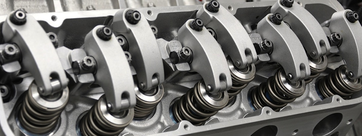
The Edelbrock heads were ported by Curtis Boggs at Race Flow Development and assembled using Ferrea valves and PAC 1300 Series dual springs, 500 Series titanium retainers and locks.


Left to right: Extra machine work on the heads included opening up the counter bores for large-OD nuts, adding clearance for pushrods and machining the receiver grove for the O-ring. Finally, the Jesel rocker arms were clearanced for large OD pushrods.
“We run a larger nut to increase the integrity of the stud threads,” explains Neelen. “With a smaller nut, it can get to a point where you’re not stretching the fastener but deforming the nut threads.”
Final assembly was rather routine from that point. Cometic copper head gaskets and ARP hardware are used to help maintain cylinder sealing. The remainder of the valvetrain, including Manton pushrods and Jesel rocker arms were installed. Fel-Pro supplied the remaining gaskets as the Granatelli Motorspsorts billet valve covers and Wilson intake manifold were installed. The top end also included a Wilson throttle body, Billet Atomizers fuel injectors and MSD distributor. With the dry-sump drive belt in place and Driven BR30 oil in the tank, the engine was ready for break-in and a couple dyno pulls without the supercharger.


The heads were installed on top of Cometic .060-inch thick copper gaskets and tightened with ARP hardware. The gaskets were delivered blank, allowing LME to drill the proper water passages and head-bolt holes, as needed.
“It was more convenient for us to run coil packs on the dyno with the Holley Dominator ECU, although the distributor was in place with the Jesel drive,” explains Neelen. “First we set the cold lash, then started the engine to check for leaks, noises and any other obvious problems.”
In warming up the engine, the dyno operator upped the load slightly and continued to increase the rpm gradually to draw down the engine and help seat the rings.
Break-in and dyno pulls
“As soon as we got heat in the head gaskets, we killed the engine and let it cool to ambient temperature,” says Neelen. “Then we took off the rockers and retorqued the cylinder heads. This helps get a real bite on the O-rings. Also gives us a chance to make sure oil is getting to the heads.”
The rockers were reinstalled and adjusted before the engine was fired and warmed up again. Then the dyno operator continued to vary the load and rpm, using mostly experience as a guiding hand.


The custom Wilson intake manifold and 123mm throttle body were installed along with the MSD distributor. The intake includes 225-pound injectors from Billet Atomizers and Wilson fuel rails.

The engine was broken in and checked for leaks on the LME dyno. With a base tune and no supercharger, it pulled almost 830 horsepower.
“We call it a lifecycle test,” adds Neelen. “Then we check lash again. Most of the dyno time is inspecting and monitoring the valvetrain.”
Running VP Racing Q16 race fuel, LME stars with “baby pulls,” bringing the engine up to 5,000 or 6,000 rpm while monitoring and adjusting fuel and ignition. The team also cuts open the oil filter to inspect for any metallic particles. Driven XP9 oil was used for all the dyno tests after the break-in.
“We keep adding timing and taking away fuel until it’s happy,” says Neelen. “We have 10 O2 sensors to monitor everything and make sure one injector doesn’t go crazy. We watch it especially close under initial startup to make sure that a cylinder isn’t getting washed down.”


Driven BR30 break-in oil was used for the initial startup with XP9 used in the full-pull tests. Test fuel was VP Racing Q16. LME also retorqued the heads after the break-in runs.
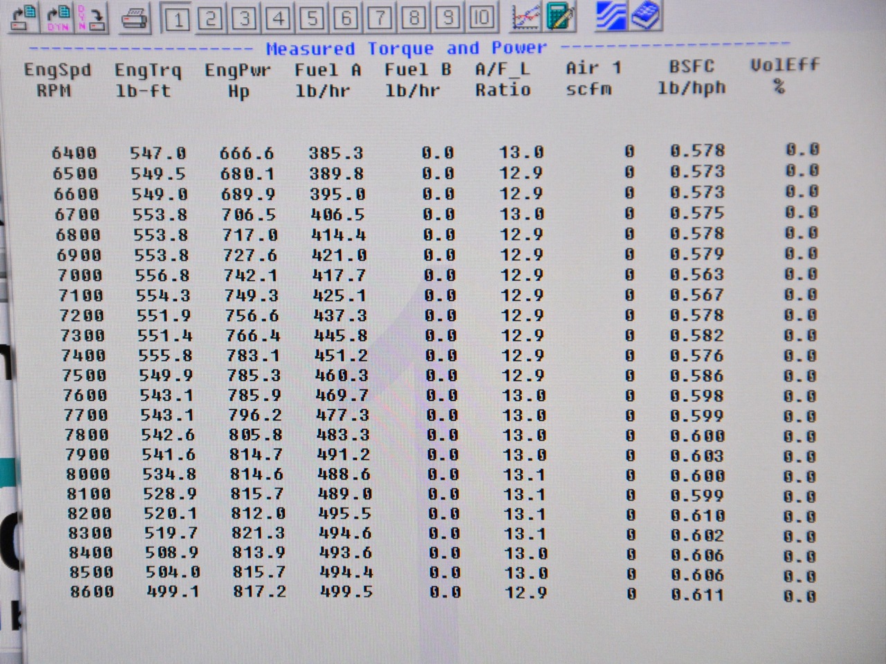 One of the final naturally aspirated pulls resulted in 821 horsepower at 8,300 rpm. Word is
“The power numbers are really inconsequential right now,” sums up Neelen. “But it is cool to know it made over 800 horsepower at 10:1 naturally aspirated. It should hit 9,500 with boost at the track and pick up 1,000 horsepower with the blower.”


From left: The LME engine was installed into BlownZ along with custom stepped headers and plumbing to support the large intercooler mounted as close to the throttle body as possible.
The fresh 400ci LME engine was mated to last year’s F1X when the BlownZ crew installed the engine in the revamped chassis. The new F1XR was still being prepped, allowing the team to make a few shakedown passes at the NMCA opener at Fontana. Kooks built a set of stepped headers (2.125 to 2.250 inch) with a 4-inch collector, 4.5-inch Vibrant Performance mufflers and “bullhorn” outlets. On the inlet side, the team used Race Parts Solutions 5-inch pipes to route the compressed air from the ProCharger through a Chiseled Performance air-to-water intercooler and then into the Wilson throttle body. At the NMCA seasonal opener, Blown Z qualified fifth with an 8.56 but quickly improved on that mark with a 7.52/190 mph with a first round victory. Steady improvements are expected throughout the year. You can follow along by checking in on the BlownZ update page.
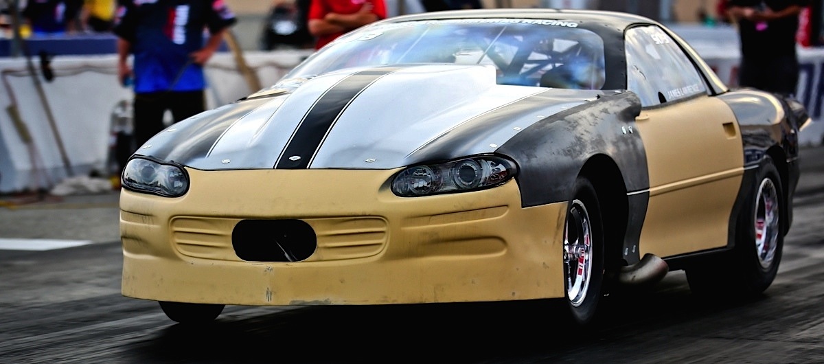
The BlownZ crew didn’t have time to apply the new livery for the NMCA 2014 opener at Fontana, but the car ran a 7.52 and set the stage for consistent improvements over the season when the F1XR is installed.


