
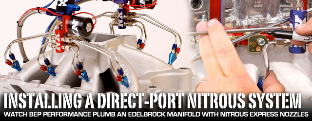
While recognizing that direct-port nitrous-oxide systems are more efficient and offer the potential for bigger shots of horsepower, many enthusiasts are often discouraged by that pesky task of plumbing the intake manifold. No doubt, it’s a time-consuming and somewhat intimidating chore; however, bending and cutting stainless-steel tubes are basic trade skills that can be learned with a little practice and patience. In most cases, the rewards will be well worth the effort.
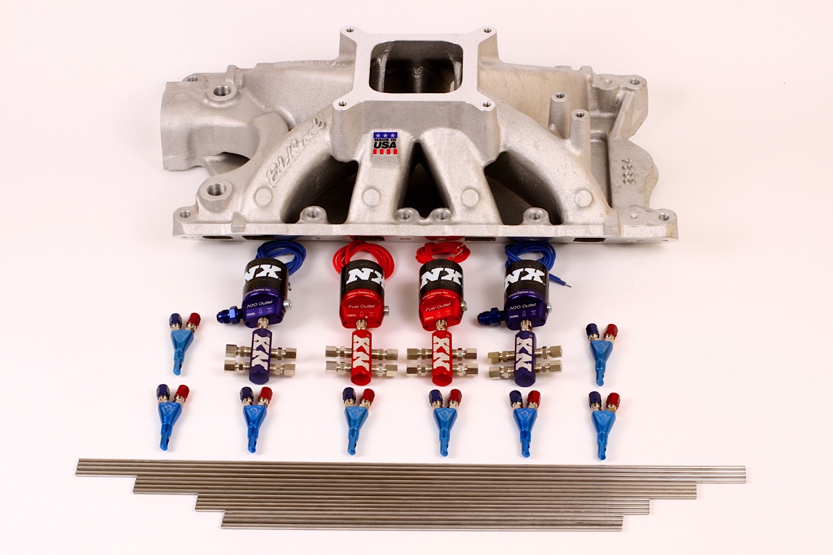
Here are the main components for the install: an Edelbrock Super Victor 351W intake manifold (PN 2924) and a Nitrous Express direct-port kit (PN 90006-10) that comes with four solenoids, eight Shark nozzles and plenty of stainless-steel tubing. Not shown are the related hardware and electrical accessories to install the system on a vehicle.
“A direct-port system is a lot more complex than a plate system,” explains Garrett Magers of Nitrous Express. “The individual nozzle system is superior in the fact that that it gives better cylinder to cylinder distribution.”
To recap, there are two popular methods of introducing nitrous oxide — also nicknamed “squeeze,” “spray,” “on the bottle” or the ever entertaining “nawzzzz” — into a performance V8 engine fueled with a carburetor. (Nitrous systems for EFI engines may be set up differently, so this how-to story will focus on carb applications.) The first is with a spacer plate that is mounted between the carburetor and intake manifold. The plate supports two spray bars — one for fuel and one for nitrous oxide. Two solenoids are also needed, one for the fuel side and one for the nitrous side. When actuated under wide-open throttle, the solenoids allow the fuel and nitrous to flow into the spray bars. When discharged from the spray bars, the fuel is mixed with the oxygen-bearing nitrous and then introduced into the intake manifold plenum.
Superior system
It makes the most horsepower with the least amount of nitrous.–Garrett Magers, Nitrous Express

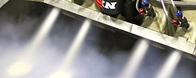
A direct-port system blends the nitrous oxide with the fuel using eight separate nozzles that are mounted near the ends of each of the intake runner. Direct-port, also sometimes referred to generically as a “fogger” system, has the big advantage of being tunable for each cylinder. In a plate system, the flow of fuel and nitrous are controlled by single jet for each spray bar. In a direct-port system, each nozzle can be tuned with different sized jets if the engine builder needs to compensate for uneven air/fuel distribution.

The kit also comes with a 10-pound nitrous bottle, a NX Lightning 45 bottle valve and supply lines. The bottle-warming blanket (PN 15941) is sold separately.
“This is great for intakes that have different-length runners,” adds Magers. “Also, direct-port systems usually ‘hit’ softer upon the initial activation, which can aid with traction in high-horsepower nitrous applications.”
More aggressive setups run two or more stages of nitrous — even combining both plate and direct-port systems. Multi-stage layouts allow for more control of the nitrous application to help maintain traction under wide-open throttle. In the spirit of keeping it simple for this story, only a single stage will be installed.
Nitrous system design
The two main components in a direct-port system are the intake manifold and the nitrous kit. While direct-port can be installed on a dual-plane intake, the majority of applications are on single-plane intake manifolds where the open plenum and free-flowing designs are more conducive to making high-end horsepower. A more practical choice for engines with dual-plane intakes would be a plate system.
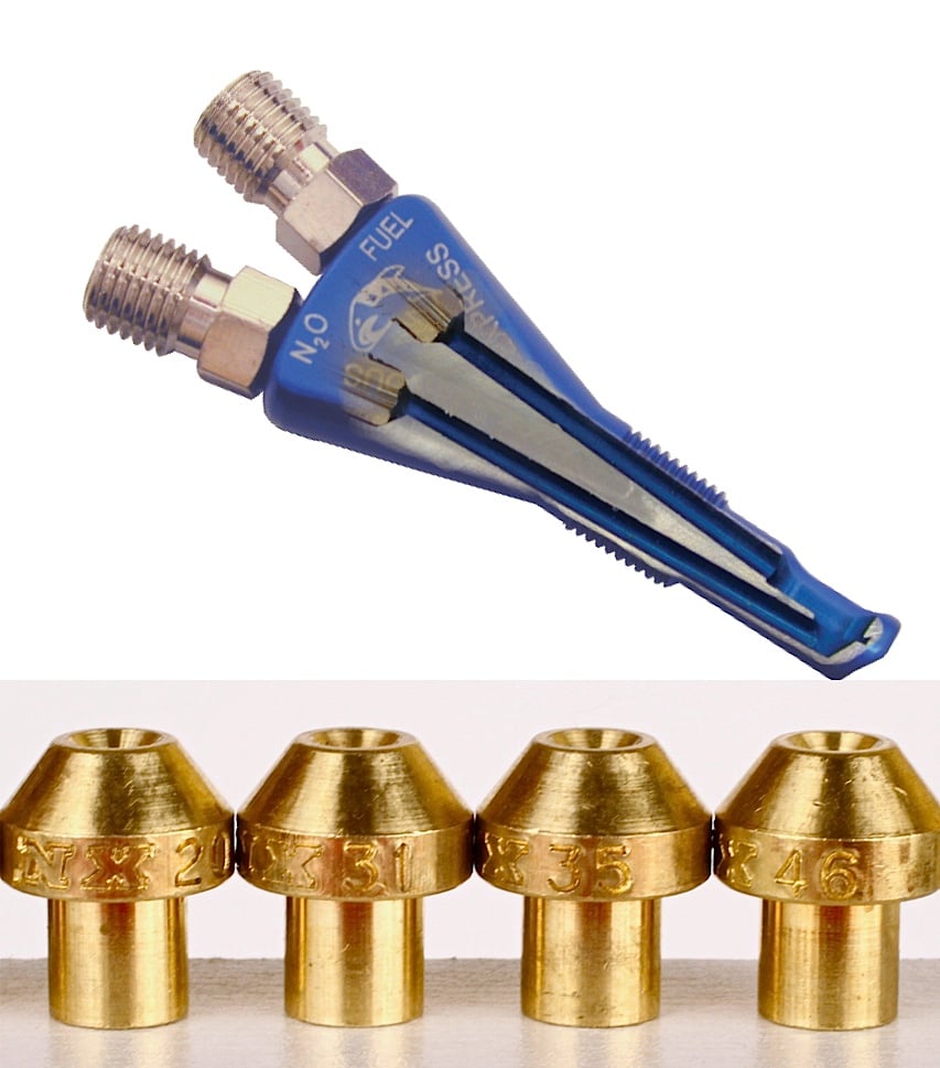
Here’s a cutaway of the NX Shark nozzle. Note how the nitrous and fuel are mixed. The amount of the nitrous and fuel are controlled with different-sized jets (the kit comes with 10 sizes) positioned on the nozzle inlets.
Soon to be featured on EngineLabs will be a 428ci Windsor street-engine build. A 150-to-250-horsepower shot of nitrous is planned as part of the dyno testing. Fitting perfectly into those goals are an Edelbrock Super Victor intake manifold (PN 2924) and a Shark direct-port kit from Nitrous Express (PN 90006-10).
The Super Victor is suited for 4,500-8,500 rpm runs and is designed for large-displacement 351W platforms on a 9.5-inch deck height. The 428 engine project will also be using Edelbrock Victor Jr. cylinder heads, so there is strong compatibility in selecting the Super Victor for this direct-port install story. The runners feature a generous 3.2-square-inch cross sectional area, and bosses for nitrous nozzles are cast into the manifold. There’s also plenty of material in the runners, should you choose to port the cylinder heads. The manifold also looks sharp with a satin finish and features a standard square-bore, 4150-style carburetor mounting pad. Total height is 6.25 inches, so it should fit under the hoods of most popular Ford musclecars.
The NX kit features the patented Shark nozzle that is suitable for high-horsepower applications. This proprietary design mixes fuel and nitrous before exiting the nozzle body. Other nozzles may have separate outlets for the nitrous and fuel.
Making horsepower
“It makes the most horsepower with the least amount of nitrous,” explains Magers. “It accomplishes this by having the most direct flow path inside the nozzle, and it also does the best job of using the energy in the nitrous to atomize the fuel. Every engine tuner will tell you, the better the fuel is atomized the more power you will make.”
The kit comes with a 10-pound bottle (different sizes and types of bottles are optional), stainless steel tubing, four solenoids, four distribution blocks and all the necessary electrical connections and hardware.

What is Nitrous Oxide?
Nitrous oxide is a normally gaseous molecule comprised of two nitrogen atoms and a single oxygen atom, hence the symbol N2O. When compressed to around 900 psi, nitrous oxide becomes a liquid and can be stored in convenient bottles. Nitrous oxide is not a fuel; in fact, it’s not even flammable. Rather, nitrous oxide is an oxidizing element that introduces more oxygen to the combustion chamber; thus, allowing the engine tuner to add an appropriate amount of additional fuel to make more horsepower. That’s why a nitrous system — whether plate or direct port — has plumbing and controls for both nitrous oxide and the fuel. As a matter of organization, the blue fittings and solenoids are for nitrous and the red side is always for fuel. EngineLabs will have more on setting up a nitrous system when the manifold is installed on a 428ci Ford Windsor and dyno tested.
“You will need a drill and drill bits, as well as a 1/8 NPT tap. You will also need a tubing bender, tubing cutter and flaring tool,” says Magers. “Take your time. Try to find someone who has experience with this that is able to give you some helpful advice. Usually machine shops can help with the drilling/tapping if necessary. Measure twice and drill the holes once. The NX Tech line is just a phone call away, don’t hesitate to call.”
That advice led us to Alan Bessant and BEP Performance in Anaheim, California. While the manifold could be drilled and tapped on a workbench or shop drill press, it’s best when plumbing your first intake to work with a competent machine shop to prep the intake. A Bridgeport-style mill will ensure accurate and consistent nozzle mounting locations. And if the shop is really experienced in high-horsepower engines, you can get some solid advice and experts tips on routing the lines.
Drilling and tapping the holes is somewhat time consuming due to the constant changing of the bits and tap. The first hole took the longest as Bessant tested the thread depth numerous times before determining the proper position for the nozzle outlet in the intake runner. One could drill all the holes first, then tap them to save time, but performing all the tasks on the runners one at a time ensures consistent alignment.
Once the manifold is drilled, tapped, cleaned and fitted with the nozzles, the artsy side of the project begins. The distribution blocks need to be positioned, and then the tubes are cut, bent and mounted between the blocks and nozzles. Every manifold will be plumbed differently, and that’s why the tubes are plenty long — you may need to try different approaches. Most experts suggest fitting the inside runners first, as they have the tightest and usually most difficult bends. Bessant likes to plumb the outside runners first, as they are the easiest and the leftover tubing can be used to rework the inside runners if problems arise. Following conventional wisdom, we started with the inside but ended changing our strategy after the first routing attempt.
Just do it!
When setting up the plumbing, don’t forget to account for the carburetor, linkage, fuel lines, valve covers and even hood clearance. This manifold will be used mostly for dyno testing, so we could open up the bends a little. Take time to search the Internet for photos of other intakes plumbed with direct port to get ideas. Nitrous Express has an excellent gallery on at www.nitrousexpress.com. You have some flexibility in mounting the solenoids, including under the distribution block and at a 90-degree angle.
While direct-port nitrous is more expensive and labor intensive, the results are well worth the effort for both performance and aesthetic purposes. The system is much more tunable and provides plenty of power. At the same time its aggressive yet elegant appearance adds distinction to the engine bay. Follow along as BEP Performance plumbs an Edelbrock intake with a Shark direct-port nitrous system from Nitrous Express.


Start with a level support on the mill and secure the manifold along the intake flange. Since the intake flanges are at 90 degrees to each other, the drilling will be perpendicular to the ports when the manifold is properly squared. However, be aware that some applications may required “tilting” the nozzle towards the carburetor 1-to-1.5 degrees to clear the valve covers. Bessant double-checks to ensure a 1/8 NPT on the nozzle, then applies machinists dye to the nitrous bosses at each port. Bessant locates the center point of the port, about 1.5 inches up from the flange, and uses the calipers to scratch a crosshair.


Bessant drills a pilot hole using a 7/32-inch bit, then enlarges the hole using an “R” bit, which is dedicated to the 1/8 NPT tap. The R bit measures .3390-inch, but don’t be tempted to use a 21/64-inch (.328-inch) or 11/32-inch (.343-inch) bit, especially the larger bit -- which could leave insufficient metal for the threads and result in leakage. Bessant then installs the 1/8 NPT tap and hand turns the mill to start the first two or three threads. Don’t forget to lubricate the top, and and don’t tap the entire length of the hole!


Bessant constantly the checks the depth of the threads by removing the tap and inserting a nozzle. He settles on a position where the nozzle won’t interfere with airflow but also not crowd the spray against the port roof. Once the proper depth is determined, Bessant marks the tap with tape to use as a guide in tapping the remaining holes.


When one side of the intake is finished, Bessant flips the manifold over and secures it to the mill’s table. Again, shown from left to right, is a quick review of the drill and tap process: Start with a 7/32-inch drilled followed by the R bit. Use the mill to start the 1/8 NPT tap, then use conventional T-handle to finish the thread depth. Note the blue tape that serves as a depth gauge for the tap threads.


The hole openings are deburred, then the intake is thoroughly washed and blown clean before the nozzle threads are treated to thread sealer and installed into the intake. The nozzles are positioned to flow with the runner direction, not vertical to the manifold flange, or straight up and down. The latter may look more symmetrical for aesthetic purposes, but also may hamper performance.


The solenoids are mated to the aluminum distribution blocks with male-male fittings, then each block is fitted with four male-male fittings to accept the stainless-steel lines. Thread sealer is used to prevent leakage. One end of all the 3/16 stainless steel lines are flared 37-degree tool, then fitted with a B-nut and a color sleeve.


Determining the position of the solenoids is somewhat of an art and skill. It’s always helpful if the actual longblock is available to double check clearances and visual appeal. The eventual engine that this manifold will serve wasn’t available, but Bessant had a 351 Windsor on the dyno and made a few visualizations using a pair of solenoids. The decision was made to get the fuel blocks close together and stagger or offset the solenoids. Bessant first applies slight bends in two of the shortest tubes that would match up with the desired position of the nitrous solenoid. He then marked the tubes for the 90-degree bend to the intlet fittings, made the bends and cut the ends at the appropriate length. Note that a representative carburetor is mounted to manifold to help judge clearances.


Always leave yourself options. Once the solenoid is positioned, lines for the outside runners were mocked up. Bessant saw a better way and decided to swap the top and bottom inlet locations. While the cameras were away, he finished up one side (bottom photos). The blocks look great side-by-side but clearly one of the solenoids would have to be offset for clearance -- a decision that would be made after the other side was plumbed.


Tubes from the first side are used as guides for bending the other side. Bessant also uses the markings on his bending tool to duplicate the bends as well as using straight lines to mark for bend center points.


The tube ends that go to the distribution blocks should be deburred after cutting, then fitted with the compression fitting and nickel-plated sleeve. To install the line, place the desired jet on the nozzle, then position the line and thread sleeves accordingly. Before the manifold is taken to the dyno, all lines will be removed and all the components will be cleared of any leftover debris with compressed air. At that time, the tuning team will determine the proper jet sizes before the system is reinstalled.


At left is the manifold with all four sets of lines and distribution blocks fully plumbed. We played with different ideas for offsetting the fuel solenoid and settled on positioning it forward using 90-degree male-male fittings, which Nitrous Express supplied along with its own sealant.


Here are various views of the completed project. As mentioned earlier, the solenoids will be removed so that the lines can be blown clean with compressed air before going to the dyno. This manifold will go on a big-inch Windsor (around 428 ci), which is currently under construction. When the engine is completed and ready to run, the dyno tuners will decided on the appropriate nitrous boost and jet the system accordingly.


