 The intense specialization in today’s premium engine building demands collaboration throughout the entire process. Crankshaft manufacturers need to know who’s casting the block and pumping the oil. Piston designers need to know what’s under and above the crown. And intake manifold fabricators definitely need to know the intricacies in the cylinder head.
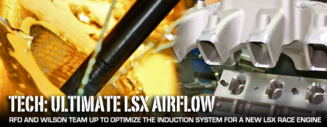
Such a cooperative effort was essential to plan out the specifics for a new engine that will power the Blown Z 275 drag-radial project vehicle. The goal is a supercharged 400ci powerplant capable of 1,800 horsepower. Since induction and airflow is key to horsepower production, the obvious starting point for the discussions focused on the cylinder head and intake manifold.
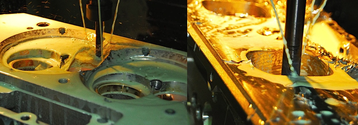
RFD has proprietary CNC programs for machining the combustion chamber and cylinder head ports from the base Edelbrock casting.
“Everything is custom these days,” says Curtis Boggs of the Virginia-based Race Flow Development (RFD). “We’ll talk to the customer to get the basics of the build, such as engine size and rpm range. Then everything is modified for the customer’s application.”
We can really customize the head down to the smallest detail.–Curtis Boggs, RFD

“We talked to Curtis quite often on this project,” adds Nick Doll, an airflow specialist at Wilson Manifolds. “I need to know the head’s true flow potential, the primary choke area, expected horsepower at rpm and general sizing of the head.”
“I do work closely with Wilson,” echoes Boggs, who supplied a set of “manifold heads” for mockup purposes at the Wilson shop. “They’re very much on their game, and we’ll discuss port sizes.”
LSX race engine foundation
The engine is based on a GM LSX block from Pace Performance and will be assembled by Late Model Engines (LME) in Houston. Internals include a Callies billet 3.75-inch stroke crankshaft, 6.050-inch GRP aluminum connecting rods, 4.125-inch Diamond pistons (10:1 compression ratio), Total Seal rings, ARP fasteners and Clevite bearings. The bottom end consists of a Dailey pan and 6-stage dry sump while the 60mm Comp roller cam will be turned by a Jesel belt drive. Other short-block components include SCE copper head gaskets, an ATI damper, Jesel lifters and pushrods, Fel-Pro gaskets and a TCI starter. In the car, the engine will be sparked by an MSD ignition and exhaust gasses will be routed through Kooks headers.
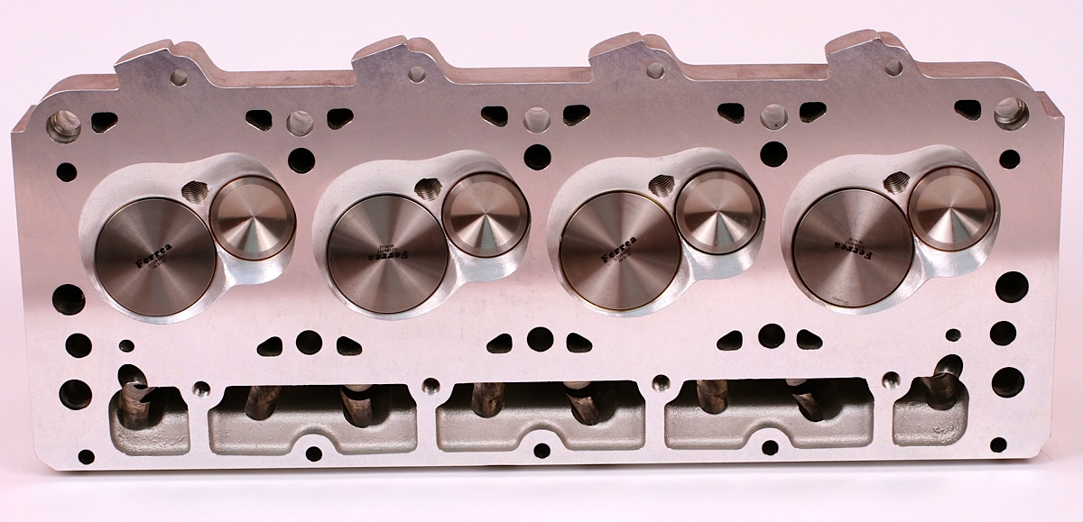
Here are closeups of the combustion chamber and ports following the CNC machining at Race Flow Development. Note the MoldStar bronze valve seats.


Here are overall views of the intake and exhaust sides of the completed head. RFD doesn’t release flow numbers as they don’t always tell the complete story of managing airflow. Based on the Edelbrock Victor Pro Port LSR casting, the head features the GM SB2 valve-cover footprint.
Strong selection of port designs
“I have six different port combinations for the intake and exhaust on the Edelbrock LS-R head,” explains Boggs. “And from those port combinations I can cut to six or seven different sizes on the CNC machine. We can really customize the head down to the smallest detail.”
From the outset, Boggs knew the engine would be boosted with a ProCharger F1X turned by a Chris Alston reverse-gear drive.
“But it’s kind of limited since they’re not running the biggest blower possible,” adds Boggs. “So you start making considerations for that; such as, you don’t put in the biggest exhaust port. You still have to size them correctly as bigger isn’t always better.”
The heads will be assembled with Ferrea titanium 2.250-inch diameter intake valves and Super Alloy 1.600-inch exhaust valves. The combustion chambers are designed to be as small and efficient as possible at 52cc.


The CNC-machined, lightweight titanium intakes are heat treated and stressed relieved in addition to being treated to a propriety chrome nitride (CrN) coating that helps provide an insulating barrier to high temperatures and helps dissipate heat along with protecting the valve-guide surfaces.
“Even with dynamic forces and valve-flex stresses in a boosted engine, there’s no delaminating or flaking,” says Ferrea’s Zeke Urrutia.
If the head has limitations, we might be able to compensate with manifold design. — Nick Doll, Wilson
The intake valves feature a 6.350-inch long, 5/16-inch diameter stem and a hardened tip, which negates the need for a lash cap. The Super Alloy exhaust valves measure 1.600-inch diameter and come with a 6.300-inch long, 11/32-inch diameter stem. All 16 valves are radial grooved and have .300-inch tip heights with hardened tips, which negates the need for lash caps. On the advice of Boggs, Ferrea cut the exhaust valves with a .080-inch margin and a 50-degree seat (.0600-inch width). The intake valves were cut with a .060-inch margin and 55-degree seat (.060 -inch width). There’s also a 35-degree back cut (.060-inch width) on the intake valves. These cuts will match up with the MoldStar bronze seats that Boggs installs on the heads.
“On a high-boost engine, you don’t put a 60-degree seat because it’ll tear it up,” warns Boggs. “Valve sizes are based on the pressure differential you’re dealing with. If you have a 12-71 screw blower, that will create a tremendous amount of cylinder pressure and you have to exhaust that. It’s not only the boost level but the volume you’re moving. Valve size itself is not the magic number. Valve sizes are in direct proportion to the throat and port area.”
Working with boost
“Limited ProCharger motors are a little different,” Boggs continues. “They’re not moving the same volume as a screw blower, so you tend to modify the valve and port sizes because you’re dealing with different volumes. Even F1X combos will be up against the max flow of the blower as a limit, so efficiency of the entire combination is just as important as a naturally aspirated combination.”
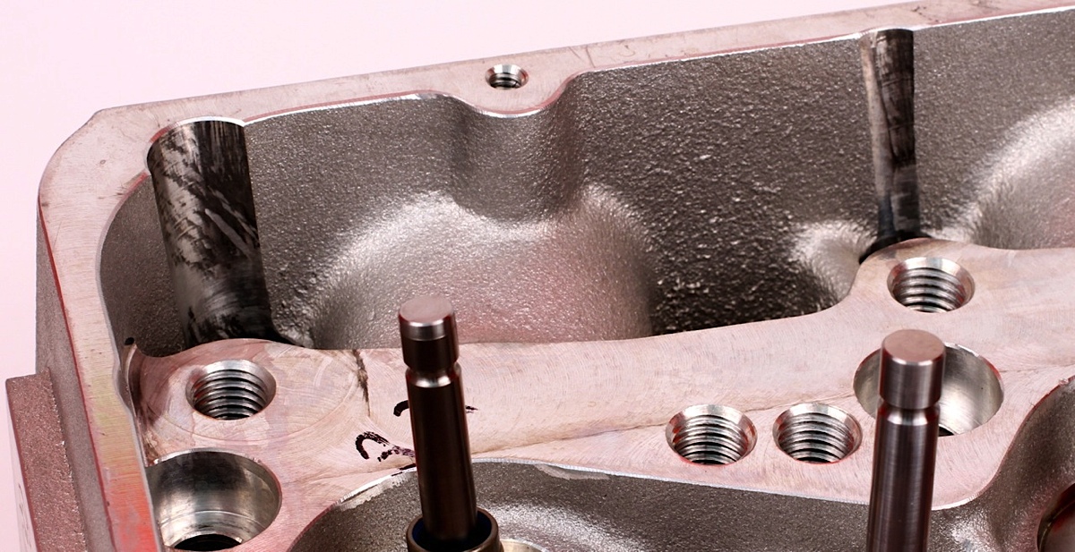
Some notching on the valve-cover rails is required to clear the pushrods, and the head is machined for a 1-piece Jesel rocker stand.
Boggs works off a spreadsheet he’s built over 35 years of porting head that matches up different combinations to help calculate the port and valve sizes.
“It’s not as simple as putting numbers in a program and that’ll tell you the right cross-sectional area,” explains Boggs. “It’s much more complex than that. Now we get into something I discuss a lot with the customer, and that’s the engine’s personality.”
Boggs offers a scenario where a 355ci engine from a dirt-track late model is compared to a 355ci drag-race engine. The latter requires high-rpm power to get the car down the track through gearing. The late model has to come off the corner with strong mid-range power and provide plenty of snappy throttle response for the restarts.


Considerable work was performed on the Chevy Performance LSX-DR casting to achieve the desired runner lengths and plenum volume. Since the DR casting is made for a different bolt pattern, the original flanges cut off with a bandsaw, then the runner ends were milled with a 45-degree cutter to provide a chamfer that will mate up with a groove in the custom flange.
“The cylinder heads on those two identically sized engines are absolutely opposite. Even if they’re both going to make peak power at 8,000 rpm, they’re going to take drastically different cross-sectional areas and valve sizes.” explains Boggs, who stresses the need to design different mach or air-speed indexes, as an example.
With the ports shaped and sized for the boost levels, Boggs next focused on the combustion chamber where he has a simple maxim: keep it as efficient as possible.
“You see in the industry a number of different combustion chamber designs,” offers Boggs. “For a ProCharger combo I tend to do it with piston design. In this case, we’ve got a small, very efficient combustion chamber. Obviously, you want to direct the combustion over the center of the connecting rod as much as possible. You don’t want side loads on the pistons. A nice, conical dish in the piston tends to center the charge.”
Teaming with Wilson for intake manifold
Boggs uses CNC machines to shape and size the ports and cut out the combustion chamber, which ended up at 52cc. Information on the latter will be given to the piston manufacturer to ensure proper compression ratio. Boggs also works with the customer on cam profiles to complement the airflow.
“This is a custom shop, so I don’t like to just sell a set of heads and make the customer figure out how to run them,” adds Boggs. “We’ll work with cam specs and give feedback on other engine factors. A large part of RFD is professional race-team consulting.”
Of course, teaming with the intake manifold supplier is just as critical, especially when working with boosted applications or situations where rules play a major role in the engine design. For Blown Z, that partner is Wilson Manifolds out of Ft. Lauderdale, Florida.


Note that the welder wears gloves while positioning the manifold on the flanges, which are bolted to the heads. The manifold was treated to 350-degree oven to help prevent warping during the TIG welding process. Immediately after the final weld, the manifold is returned to the engine and covered with a heat blanket, again to reduce the chance of rapid cooling and warpage. Not only is the manifold welded to the new flanges, but additional metal is built up around the runners. After cooling, the manifold goes back to the mill to ensure the ports come in at 4-degrees from the flange.
“If the head has limitations, we might be able to compensate with manifold design,” says Doll. “That’s the kind of things we’ll discuss with the cylinder head specialist.”
Wilson started with a Chevy Performance manifold (PN 19257851), which was obtained from Pace Performance. This casting is designed for the LSX-DR cylinder heads and needed some surgery to fit the Edelbrock heads as well as match the flow characteristics of the RFD porting.
“It was the easiest choice but it’s still not long or wide enough,” explains Doll.
The obvious concern was the unequal runner lengths between the middle and outside cylinders. Wilson technicians first shortened the length of the outside runners by 1.5 inches to help equalize the airflow.


Top left photo is the stock GM casting, followed by photos showing the scars from where Wilson cut and welded to enlarge the plenum and reduce the length of the outside runners. After the fabrication is complete and all the welds are ground and polished, the ports, plenum and other openings are covered. The manifold is then sand-blasted (bottom right) to give the finish a cast appearance.
Equalizing the runners
“When you shorten the outside runners, you also get a larger plenum,” says Doll, “which was also the effect we were going for.”
The next step was cutting off the bolt flanges and prepping the manifold to be welded to a new set of custom mounting plates, which were cut with chamfers around the ports. The ends of the manifold’s runners were also cut with a 45-degree tool to match the chamfers. Before welding, the new plates were bolted to a set of similar LSR heads on mounted on a dummy block, and the manifold was heated in an oven to help prevent warpage during welding.


Additional hand grinding gave the ports and plenum their final shapes and sizes.

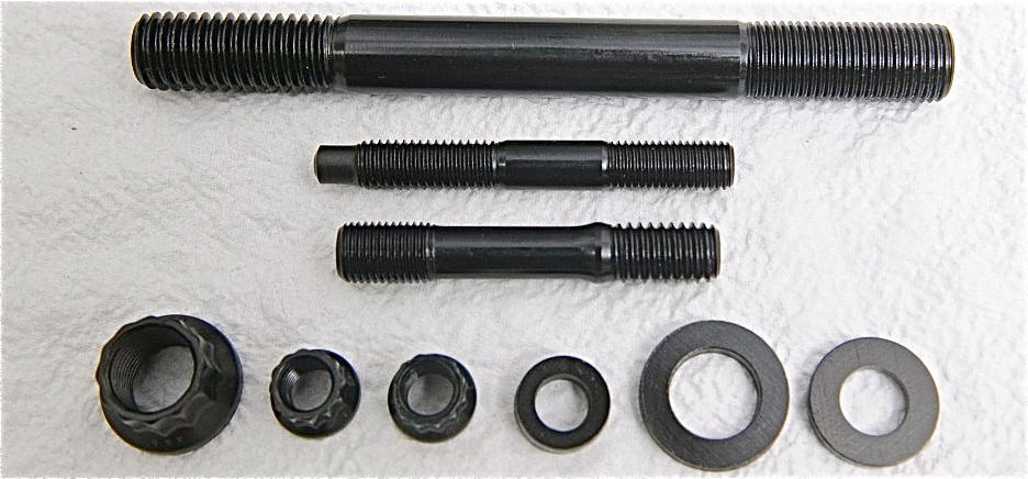
Custom ARP Head Studs
Securing the RFD-preppped Edelbrock heads to the Chevy Performance LSX block will be a set of custom ARP studs. Three stud sizes are needed for the 6-bolt heads: 1/2-inch mains, 3/8-inch outer and 8mm inner. All the hardware is machined from ARP2000 material, which is a heavily alloyed steel originally developed for steam power plants — so it provides excellent stability at high temperatures. ARP2000 also exhibits excellent notch toughness and has a strength between 200,000 and 220,000 psi. The studs are hex-broached for easy installation and come with 12-point nuts and hardened parallel-ground washers for improved load distribution. ARP fasteners will also be used throughout the engine assembly
“When the manifold mates up with the new flange, the weld will penetrate completely through,” explains Doll. “If we didn’t put that 45-degree V and left it flat, the weld may look good but then when we grind it could cut into air pockets.”
The new flanges will be sized slightly smaller than the head’s intake ports, giving Wilson flexibility in machining the final size. The ends of the manifold runners are also beefed up with additional material.
“All that weld is to make sure that when we get the right transition angle into the port, the machining is not breaking through on the manifold,” says Doll. “Since this is a one-off piece, we’ll do it on the mill.”
The welds are ground flush and polished for a smooth appearance. All external openings are then taped off before the manifold is subjected to the sand blaster to disguise the welds and also provide a fresh-cast appearance. Final prep work includes hand porting the runners.
“The first thing we look at is rpm range and cubic inches,” says Doll. “Even though the inside and outside runner volumes will be slightly different on this manifold, they will have a same taper.”
Wilson will also finish off the interior surfaces with standard 80-grit abrasives.
Manifold runner surface choices
“With fuel injection you can make it a little smoother,” adds Doll. “But even with fuel injection, there are still pulsations. There’s still fuel running around inside that manifold. You don’t want a mirror finish.”
The fuel system includes an Aeromotive pump pushing VP Racing Fuels Q16 race gas to 225-pound Billet Atomizer fuel injectors, so Wilson machined out the manifold runners to install new fuel-injector bosses.


The fuel-injector bosses were machined down, then new bosses were welded at the desired angle. Final work included positioning the fuel-rail supports.
“You look at the approach angle of the head and the valve angles when positioning the bosses,” explains Doll. “You try to aim the injector right at the back of the valve. You don’t want the fuel to hit the wall or floor, then you end up with puddling.”
During the buildup the manifold will also be treated to Wilson fuel rails and a Wilson 123mm V-band throttle body. Controlling the fuel delivery once the engine is installed into the Camaro will be a Holley Dominator ECU.
Check back often for additional stories as LME assembles and dyno tests the engine with a goal of surpassing 1,800 horsepower.
Here is the finished intake with the fuel rails installed. Note both the exterior and interior finishes as well as the fuel-injector location and the final port and plenum shaping. Click on any photo for an expanded view.


