Designing an engine from scratch is a monstrous task; it takes the largest automotive manufacturing companies years, many dozens of millions of dollars, and thousands of engineering hours to do so.
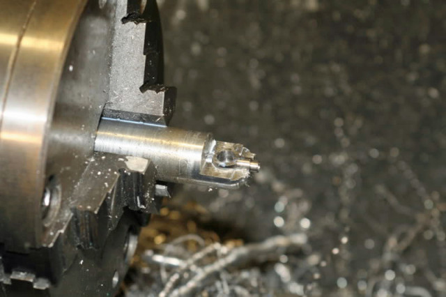
Imagine, if you will, a gentleman machinist that has a hankering to build his very own quarter-scale gasoline V8 engine, but has a miniscule engineering budget, and none of the machinery or cubic dollars that the big boys have. Undaunted, he seeks out a way to build this engine in his home shop. Without a single computer-controlled machine—every piece for this engine was built either on a manual Bridgeport mill or 90-plus-year-old Union lathe—each machining operation is a trial-and-error event that resulted in an engine that not only runs but satisfies its creator’s desires.
That machinist is United Kingdom resident Keith Harlow. “I’ve always fancied building one of these,” says Harlow.
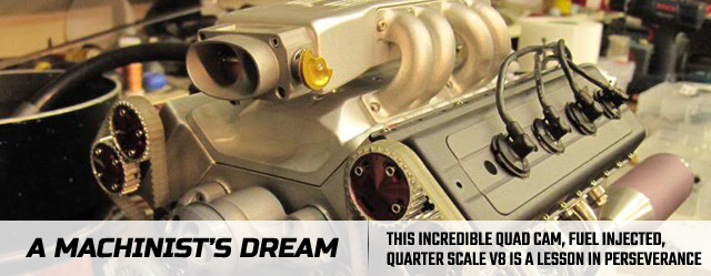
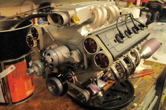
The level of detail in these pieces is simply astonishing, from the crankshaft drilled for straight shot oiling to the custom finish applied to the outside of the block's surface.
Initially, he drew up the project in CAD software, then began machining parts back in February of 2011 for the 45cc engine. The engine’s design is loosely based on the small-block Chevrolet, but after starting the machining process, Harlow decided that a four-cam overhead valvetrain arrangement was more to his liking. Changes were made on the fly to adapt the new idea; Harlow accomplished much of this build by sketching out his concepts and making many, many adjustments during the machining and build process.
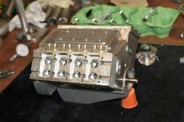
An early version of the block and head assembly, with the first of four lower intake manifolds on top.
“I went away from my CAD drawings and ended up making it up as I went along, making sketches and calculations on scraps of paper strewn across the bench. But from past experience that’s how I work best because the look of the thing is as important as it’s function, so I change things all the time to what looks best,” says Harlow.
In an interesting twist, initially Harlow spent much more time developing the external bits of the engine like the exhaust, cam covers and intake manifold before finishing up the crankshaft, connecting rods, and pistons. In this case, form and function held a balance in his mind—there was no sense building the engine unless it was going to look the part.
These are two of the intake designs that didn't make it to the final version of the engine, yet are beautiful in their own right.
Even the stainless steel headers were made in-house, with lots of trial-and error fitment.
“I wanted to do the tightest bends possible in 10mm stainless. They ended up at 16mm inside radius on the bends. The tubes were filled with low melting point metal before being bent. The bends are so tight that they still distorted slightly but most of the defects filed out. I started with copper pipe to get the angles, then unfilled stainless to work out the distance between the turns, then pulled the filled tubes,” he explains.
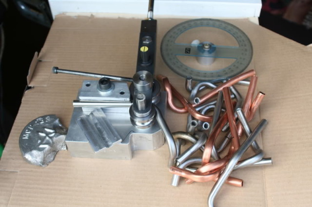
Headers were bent using this tubing bender. They were filled with low-melting point material and set aside to cool before the bending process. This allowed the tubes to stretch without cracking, then the material inside was melted out.
Once the first header was constructed, he says it was quite the process to design a second header that was a mirror-image of the first one, and it took over 18 feet of tube to get both headers completed.
Multiple intake manifold designs were constructed; Harlow invested a lot of time on the first system that sounded good in theory but wasn’t up to his visual standards before designing a second system that used a box-style intake on top of short runners, and a third system that used eight individual runners atop the second intake’s lower manifold design.
Various views of the manifold runners during the construction process.
None of these were deemed acceptable for the completed engine; finally the fourth system that he developed is modeled after Edelbrock’s High-Flow TPI intake for the small-block Chevrolet and required all-new lower and upper manifolds to be made. This intake took somewhere in the neighborhood of 60 hours to manufacture.
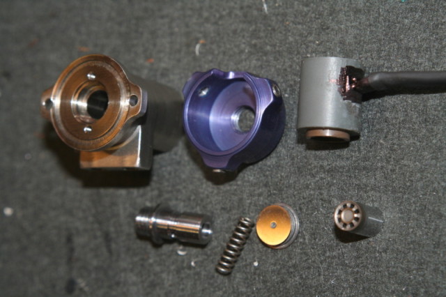
Even the oil pump was made in-house, and was one of the largest challenges of the whole project due to the small size of the internal components. After finally coming up with a design he thought would be ideal, the pump was tested with a drill and put out over 200 psi, which required the installation of a bleed valve that reduced the pressure to a more-reasonable 60 psi reading on the gauge.
Harlow even constructed miniature AN fittings from aluminum to use with the 5mm oil feed hose coming out of the back of the pump. A banjo fitting takes the oil feed from the pump to the left-side cylinder head, while the line from the filter housing to the pump is hand-bent stainless line.
Designing the flywheel and ring gear proved to be a particular challenge—Harlow’s initial flywheel design proved too wide to fit between the headers, so he had to go back to the drawing board and create a new, smaller piece.
“I wanted this engine to have a slow tickover and have a realistic overrun, so I needed a heavy flywheel, which the original was. With the small diameter of this one I made it out of tungsten alloy, which is very heavy. I think it’s about two and a half times heavier than steel. It was horrible to machine, blunting the carbide lathe tools, and snapping drills. But it feels great when spinning on the crank,” he says.
During the cam grinding process, Harlow realized that he wasn’t happy with his initial results, so he devised an attachment for the lathe to allow him to build the camshafts to his satisfaction.
“I hogged the cams out on the rotary table, using cuts at 5 degree intervals, then blended the flats in with a file. They didn’t look too bad but I wasn’t 100% happy with them, so I decided to grind the profiles to get them spot on. After hardening the cams I started making a makeshift copy grinder attachment for the lathe. This seemed to take forever, but the results were worth it. I made a full size cam lobe and then designed the linkage to move at 1/4 movement,” explains Harlow.
The cam grinder used a full-size lobe and reduced the action of the grinder down to one-quarter the size to allow for the proper dimensions on the final machined piece.
(Left) A connecting rod and bearing. (Center) Some of the valves and valve springs in assembled form. (Right) The water pump impeller.
Another challenge arose in the valve gear area; with a conventional bucket camshaft follower, he was concerned that there would be a hydraulic oil lock situation. To remedy this issue, he designed the valvetrain to allow the valve stems to also act as the sliding portion of the follower, and the tops of the valves are screwed on after the springs are installed.
In order to provide enough adjustment to get the camshafts dialed in, each camshaft pulley offers +/- 15 degrees of adjustment capability.
(Left) Before and after camshaft final machining and heat treating. (Right) The multi-piece valve and spring configuration.
He encountered huge challenges in getting the ignition to work properly. In testing, a number of carburetors and spark plug designs were tested to ensure the engine’s viability and performance—some of the plugs did not survive, and the initial test ignition was cobbled together using an HEI-style distributor, which proved troublesome and inconsistent. Eventually, Harlow engineered an old-school points ignition, which worked flawlessly.
The engine was also initially designed using a set of PTFE (Teflon) rings around the top of each cylinder liner to help seal the combustion; this design was also scrapped in favor of an o-ring at the top of each liner, compressed with a copper gasket between block and head, when the initial design failed during the ignition and run-in testing phase of the engine’s development.
In addition, the pistons are constructed with only a pair of combustion rings—no oil control rings are necessary, although determining the proper oil levels to prevent smoke was a challenge upon during the initial startup and testing periods.
A single fuel injector is used; it was an extreme challenge to construct, test, and perfect its operation and almost derailed the project before it was ever finished.
“I used a Fiat Punto injector. This flowed 150cc/min. The orifice is 18 thousandths diameter. The smallest drill I could get hold of is 10 thousandths so I stripped the injector and made a new orifice plate. Getting the sealing face flat was a pain but I did it eventually. The new injector flows 75cc/min. at 40psi,” he explains.
“I then had to make new injector internals to halve its overall length. The injector is mounted upside down to fire up into the plenum. I made a temporary central tube just to see if it worked. The tube has a pin across the bore, against which the injector fires the fuel jet. This seemed to atomise the fuel quite well.”
This configuration was tested with a manual microswitch and performed up to snuff.
And then came the last, and most difficult challenge—getting the fuel injector to work with his intended electronic control system, the MegaSquirt MS2 Extra. First the coil packs wouldn’t fire, then once he got those working his laptop would lose all communication with the MegaSquirt ECU.
“I tried foil shielding, and ferrite rings, and capacitors on the ECU, and 8k resistors on the plugs, but nothing made the ECU communicate with the laptop when the engine starts turning. I got fed up with that and so put some best guess maps in for ignition and fuelling, and after an hour it started,” he says.
Various machining operations. Look at the crankshaft coming to life!
But the communication issues persisted, so he put the engine aside for a bit and worked on another project. Eventually, he pulled the engine back out and hooked it up to a different laptop, and the problem disappeared—no more communication issues.
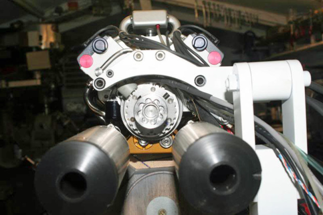
In order for the MegaSquirt MS2 engine management system to work, Harlow had to engineer a crankshaft trigger wheel to mount to the rear of the crankshaft. This view is of the rear of the engine–those large cans in the foreground are the mufflers.
“One thing I changed was to control it by throttle position sensor instead of manifold pressure sensor. There’s nowhere near enough manifold vacuum to use the MAP sensor option. There is a small trim pot on the throttle shaft acting as the throttle position sensor,” he explains.
Views under the valve cover. Is this thing a work of art or what?
The end goal of this entire project was to build a scale, fuel-injected, V8 engine, and he succeeded quite handily. But more importantly, he gained valuable knowledge for his next project—a 1/3 scale, supercharged V10 project that’s well underway. We’ll be bringing you that project as it’s completed, which Keith estimates to be about a year or so out at this point.
Keith Harlow, stand up and take a bow. The rest of us are in awe of your talent and persistence. Kudos to you, kind sir.


