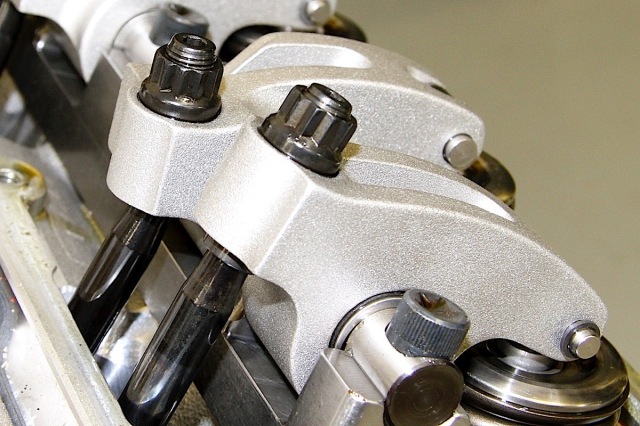
 Here’s a good story illustrating valve-lash dynamics in an engine.
Ron Quarnstrom had a Ford Windsor on his dyno at R&R Performance that was making pretty good power when he took a break to check the lash. All the valves came in around .050-inch. Apparently the engine builder mistakenly set the lash with two feeler gauges stuck together. Quarnstrom reset the lash to .025-inch.
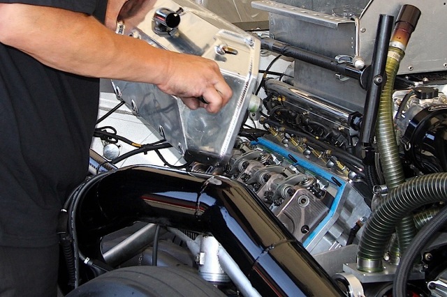
Yes, it’s a pain to keep pulling the covers but valve lash needs to be checked often on race engines to ensure optimum performance and discover potential valvetrain problems.
“And the engine lost 32 horsepower,” he remembers.
Fortunately the engine’s owner had a good relationship with a cam grinder, who used that information to fashion a cam that returned the power with a more appropriate lash that wouldn’t beat up the valvetrain.
Valve lash is the gap between the tip of the valve and the rocker arm when the lifter is positioned on the base circle of the camshaft. This gap is critical in pushrod engines equipped with solid lifters, either roller or flat-tappet, and it’s also required on most overhead-cam engines that don’t have some type hydraulic lash adjustment. Pushrod engines can also have hydraulic lash adjustment. More on that option later.
Monitoring valve lash is more about checking the condition of the valvetrain. – Steve Brule, Westech Performance
“What happens is the pushrods don’t grow but the head does,” echoes Steve Brule of Westech Performance, who has adjusted valves on hundreds of engines tested on the shop’s two SuperFlow dynos over the years. “The head is then moving the rocker arm further away from the pushrod.”
Taking a beating
If the lash setting is too loose or excessive, the valvetrain takes a severe beating. The rocker arm acts like a sledgehammer by building up momentum with the extra distance and pounds the valve tip. Much of that force is reflected back through the rocker and pushrod to the lifter. Broken lifters and burnt pushrod tips are often consequences of too much valve lash. If the lash is too tight, the intake valve may hang open.
Some engines have the valve-lash adjustment on the pushrod, like this early Hemi.
“You can also burn a valve if it’s not fully seated,” adds Godbold. “The combustion gasses act like a plasma cutter on the seat and valve face.”
With regards to cam design, lash affects the lower ends of the valve-lift profile. Those areas of the curve help “gently” open and close the valve. And if these areas of the lobe design are reduced or eliminated through excessive lash, then the lifter hits the more aggressive angle of the ramp too quickly and more stress is forced on the valvetrain. Plus, there’s a downside to overly tight valve lash.
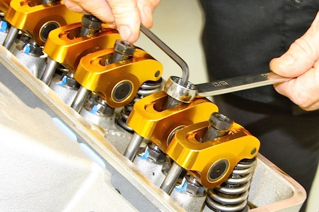
Perhaps the most popular method of adjusting valve lash is with a polylock on a stud-mounted rocker. There’s an adjustment nut and a locking screw that work together to properly position the rocker.
“We’re talking opening and seating velocity. Typically, with any collision exhibiting elastic characteristics, you want to make contact with non-zero relative velocity,” says Godbold. “Hence, you would like to be able to control both the opening and closing velocity of the system as the valve opens and closes. With zero lash, the system would be forced to have zero velocity at opening and closing, and this would limit engine performance.
“As valvetrain systems have become more rigid and allow for higher accelerations, opening and closing velocities have counterintuitively migrated down a bit,” continues Godbold. “However, the accelerations are moving the opposite direction to achieve even shorter seat timing with more area. That said, I do not see a day where we would desire a real ‘zero’ opening and closing velocity as would be required at zero lash.”
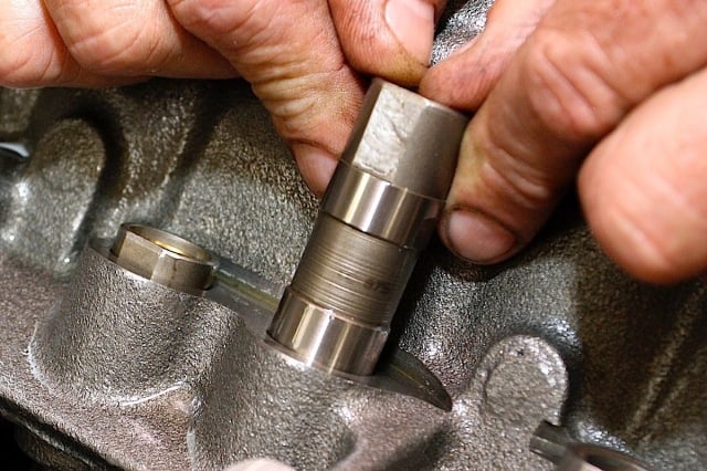
Note the pushrod guide plates in the left photo. Some engines don't have guideplates or machined slots in the cylinder to keep the pushrod in line. These engines may use self-aligning rocker arms that either have tabs on each side of the rocker body or the roller tip has integrated washers to maintain proper alignment. Self-aligning rockers are almost always used with hydraulic lifters, so lash isn't required. But if they are used in solid-lifter applications, then a feeler gauge trimmed to fit between the slots will be required.
Designing cams with lash in mind
Basically, cam manufacturers have enough data in place to design cams with a certain amount of lash built in to optimize performance.
“Each cam lobe designer has various criteria per application type that he’ll consider when designing a lobe, whether mechanical or hydraulic design,” says Chase Knight of Crane Cams. “Factors include quietness, long-term durability, valvetrain noise, reliability, rpm range, valvetrain weight and more. This is why you can find perhaps a dozen lobes from various manufacturers that will have seemingly identical lifts and durations, but actual operation and testing of each can provide noticeably different results among them.”
Overhead-cam Engines
This story focuses on pushrod OHV engines, although much of the valve-lash theory and some of the adjustment techniques apply to overhead-cam engines. As noted in the above photo, overhead rockers can have adjusting mechanisms to set the lash. Other OHC engines have hydraulic self adjusters, which can be used with finger-style rockers in some arrangements but are most often found in bucket-style setups, as illustrated below. The engine’s oil pressure is used to maintain proper contact with the cam lobe and valve in these hydraulic systems with installation and maintenance varying according to application. That’s all for another story.
“Variations in cylinder-head flow, manifolding, compression and overall vehicle application make changing the lash a good way to sort out your particular combination, just as advancing or retarding your cam would,” adds Knight.
These options could become scarce as more “tight-lash” cams are being designed – especially for endurance engines where less abuse on the valvetrain is desired.
“Going back to the idea of running higher acceleration and lower seating velocity, most tight-lash cams have lower impacts onto the valve train system, but much higher accelerations to achieve similar motion,” says Godbold. “The intended goal is greater control and lower high-frequency or high-harmonic inputs into the system that can break parts and excite the valve springs into resonance. This technique is especially beneficial with some of the larger cam journal engines and with stiffer steel rocker arm designs.”
“A tight-lash camshaft may permit the valve to initially accelerate and decelerate more quickly without being overly harsh, but may not be of practical use in situations where engine growth from cold to hot will require resetting the lash frequently,” says Knight, noting that engine materials play a critical role in such camshaft decisions. “Tight-lash cams also have a reduced lash window that can be used for testing, as once they are increased too much, reliability will deteriorate.”
Solid lifters on a hydraulic cam?
This new trend in cam design is actually drifting over to cams made for hydraulic lifters, which eliminate the need for valve lash by using the engine’s oil pressure to maintain a constant contact between the rocker and valve tip, regardless of engine temperature. When the valve is closed, the hydraulic lifter fills with oil and forces a plunger to push on the pushrod and take up any slack in the system. The lifter is designed to bleed out a little oil as needed to ensure that the valve is not held off its seat. However, at high rpm, there’s less time for the lifter to bleed off, and it could actually “pump up” with too much oil. Then the valve could be held in the open position. New designs in hydraulic lifters are being offered to take advantage of improved lobe designs.
Adjusting the preload on hydraulic lifters requires tightening down the rocker while twisting the pushrod until it feels snug. It's a little easier with the intake manifold off the engine.
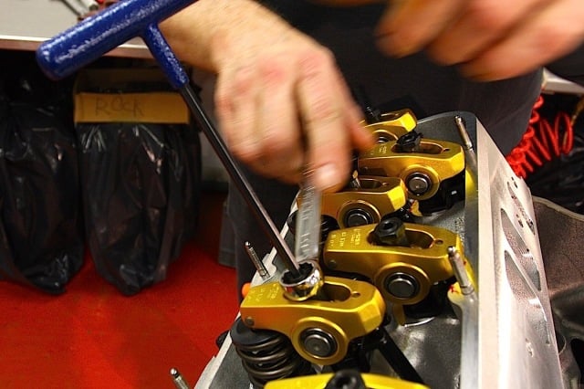
As soon as there is zero lash, the adjustment nut is turned an additional quarter to half turn to set the preload, according to the manufacturer’s instructions.
“Most of the best running hydraulic roller race engines use tight-lash solid-lifter cam designs. Over the past few years, Comp Cams has been developing several series of cam profiles that fit in the gap between traditional hydraulic style and tight lash solid roller style,” explains Godbold, pointing to the EHI and EHX cam lines that are popular in LS engines. “These work great with either a short-travel hydraulic roller tappet or a solid lifter at the tight limit of possible lash setting for aluminum blocks and heads, around 0.012-inch hot.”
“In many cases, it’s acceptable to use mechanical lifters on a hydraulic camshaft if relatively tight valve lash figures are used,” adds Knight. “Without clearance ramps on the hydraulic lobes, lash settings of .005-inch are usually appropriate. However, we do not advise hydraulic lifters to be used on mechanical camshafts. The lifters will react to the clearance ramps as they would to lobes with excessive base circle runout, resulting to premature lifter pump-up, valves being held open, a loss of power and an excess of pressure in the lifter that can break it. One possible exception might be a dedicated racing style lifter that’s produced for hydraulic lifter rule restrictions. This would have an extremely short plunger travel (.010- to .020-inch) and a quick leak-down rate, essentially acting as a mechanical lifter when in operation.”
Tedious but necessary chore
Setting the valve lash is one of the less glamorous steps of engine building and maintenance, but like other tedious chores such as setting the ring gap, they have to be executed accurately to make the best power. There are a number of preliminary checks on the valvetrain that are necessary before setting the lash, and these precautions work with both solid and hydraulic cams. Aside from checking that’s there no damage, such as a broken spring or bent pushrod, the lifters must be properly seated with no restrictions in their bores. Most important are the pushrods. They have to be straight and sized correctly to ensure proper valvetrain geometry.
Make sure the valvetrain is free of any damage and correct pushrod length is selected. The rocker tip sweep can be checked for both static and sweep position to ensure desired rocker-arm geometry.
“Pushrod length on shaft-mounted or pedestal rockers is critical,” stresses Brule. “Because you have to be within a given range. On a stud-mounted rocker, you can still get the correct valve-lash adjustment but the geometry changes.”
The most popular street-performance OHV engines generally provide one of three different adjustment mechanisms for setting lash: on the pushrod, on the pushrod side of the rocker and with the locking nut on the rocker stud. These adjusters can work with hydraulic- or solid-lifter cams, but solid cams will be addressed first.
The basic adjustment procedure is the same for all three. Rotate the engine until the lifter for the valve is completely on the base circle of the camshaft. Use a feeler gauge and the adjustment mechanism to set the desired gap and lock the setting before moving the to next valve.
Valve-lash adjustment wrenches are available from a number of sources. This one on the left is from ProForm Parts. Just slide the wrench over the locking nut and the T-handle hex drive goes in the adjustment screw. Some rocker-arm manufacturers require the locking nut to be torqued in place. This handy tool from Jesel on the right photo has a built-in torque wrench that also allows use of the the T-handle hex drive.
Most cam manufacturers call for setting the valve lash when the engine is hot. That presents a mild dilemma for builders of new engines or situations in the pit where rocker arms or valve springs were replaced. What should the lash be when the engine is cold before initial startup? Conventional wisdom calls for adding .002-inch to the hot-lash setting with an engine constructed of an iron block and heads; subtracting .006-inch for iron block/aluminum heads; and subtracting .012-inch for an all-alloy engine. This correction will allow a safe start and warmup of the engine so that the valves can be properly adjusted at the hot-lash setting.
Setting one cylinder at a time
Some engine builders prefer to set their engines cold all the time with the theory that the metal expansions differ during warmup but “cold is cold.” They achieve an optimum tune while the engine is hot, then let the engine cool down completely before measuring the lash cold and using that setting before each race.
Here's a quick review of the EO/IC method. When the exhaust valve is starting to open (left photo), adjust the intake valve. When the intake valve is just about to close, then the exhaust lash can be set. This routine also works for setting hydraulic-lifter preload. Set one cylinder at a time, either down one cylinder bank and then down the other side. Or you can follow the engine's firing order.
The step most engine builders do agree on is setting the lash one cylinder at a time. There are instruction manuals that provide a sequence with the crankshaft rotated every 90 degrees, but that gets confusing moving between cylinders and sides of the engine. If you’ve got a bump-starter switch nearby, as on the car’s firewall or on the engine dyno, then set one cylinder at a time. Some engine builders follow the engine’s firing order while others simply go down one bank and then the other. Even when hand-cranking the engine on the assembly stand, most builders prefer the peace of mind from setting one cylinder at a time.
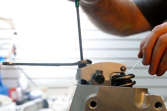
When setting the lash, be sure the feeler-gauge blade is parallel to the valve tip surface or a false reading could result.
This procedure is generally called the EO/IC method, which stands for exhaust opening/intake closing. Working with the first cylinder turn the engine until the exhaust valve starts to open. That indicates that the intake valve is resting fully on the cam base circle and can be adjusted. Then turn the engine over until the intake valve is just about to close. That means the exhaust valve is ready to be adjusted. Simply repeat this process with all remaining cylinders.
The process is slightly different with hydraulic lifters. There is no gap to set; rather, the lifter needs a “preload” to ensure that the plunger is in the center of its travel. Basically, the pushrod is rotated with one hand and the rocker arm is tightened until the pushrod is snug in place or at zero lash. Then the adjuster is turned or tightened until there is enough preload. The amount the adjusting nut is turned depends on the type of adjustment mechanism as well as the lifter. Most applications will use a 7/16-20 rocker-arm stud. A full turn of the adjustment nut moves the rocker .050-inch, so a quarter turn will provide .0125-inch preload in the lifter. The adjustment on the pushrod end of the rocker arm can be calculated in a similar manner. Jesel uses a 3/8-24 screw adjuster, which equates to .041-inch movement with each full turn.
Dealing with non-adjustable rockers
Hydraulic lifters must have oil in them before setting the preload. When assembling an engine it’s always a good idea to soak the lifters in oil for at least 24 hours to fill up the cavity. Pre-oiling the engine before startup will also fill up the lifters, but there’s one big caution.
“You have to have some light preload on all the lifters,” warns Brule. “Or else you could pop the plunger right out of the lifter body.”
Some hydraulic cam engines don’t have a traditional adjustment option as the preload is set mostly with pushrod length. As long as the heads aren’t milled or a different set of lifters installed, the preload will be correct when the lifters are installed. Watch the Comp Cams video below for a closer look at such a setup.
Want another story from R&R Performance about valve lash? Quarnstrom remembers a Ford FE on the dyno. As he went down one side of the engine, checking the lash on each cylinder he noticed that the gap increased progressively and uniformly. Front cylinder was about .028-inch and the rear cylinder was up to .060-inch. The cam was anchored relatively firm up front by the timing set, but a combination of cam rotational dynamics, soft cam bearings and wicked valve springs forced the cam to sit down lower in each of the following bearings. The engine’s owner then knew it was time to go back inside the block. Which brings up another good point about keeping an eye on valve lash.
“Monitoring valve lash is more about checking the condition of the valvetrain,” sums up Brule. “If everything is the way it’s supposed to be, it really shouldn’t change.”


