It would be sexy and cool to say that 20 years ago, BMW crafted a way to crush Porsche’s GT class dominance, using only their wits and an inline-six, but that would not entirely be the case. The S54B32 engine merely played second-fiddle to the much-protested 4.0L V8, but that is another story. A much truer statement would be that the S54 heralded the end of the line for the shrieking, naturally aspirated M50/S50 family of BMW inline sixes.
It was a design stretch from the usual hot-rodding beginnings: add bore and stroke to the old engine and add newly available technology in the form of Double VANOS (BMW speak for variable cam phasing on both of the dual overhead camshafts, capable of adjusting the intake centerline from 70-130° and the exhaust centerline from 83-128°). Add a small bump in compression (to 11.5:1), individual throttle bodies, finger-follower rocker cam followers, the previously mentioned Double VANOS, and an internally scavenged two-stage wet-sump oil pan, and this high-feature six-cylinder becomes something very special back in 2001 and still today.
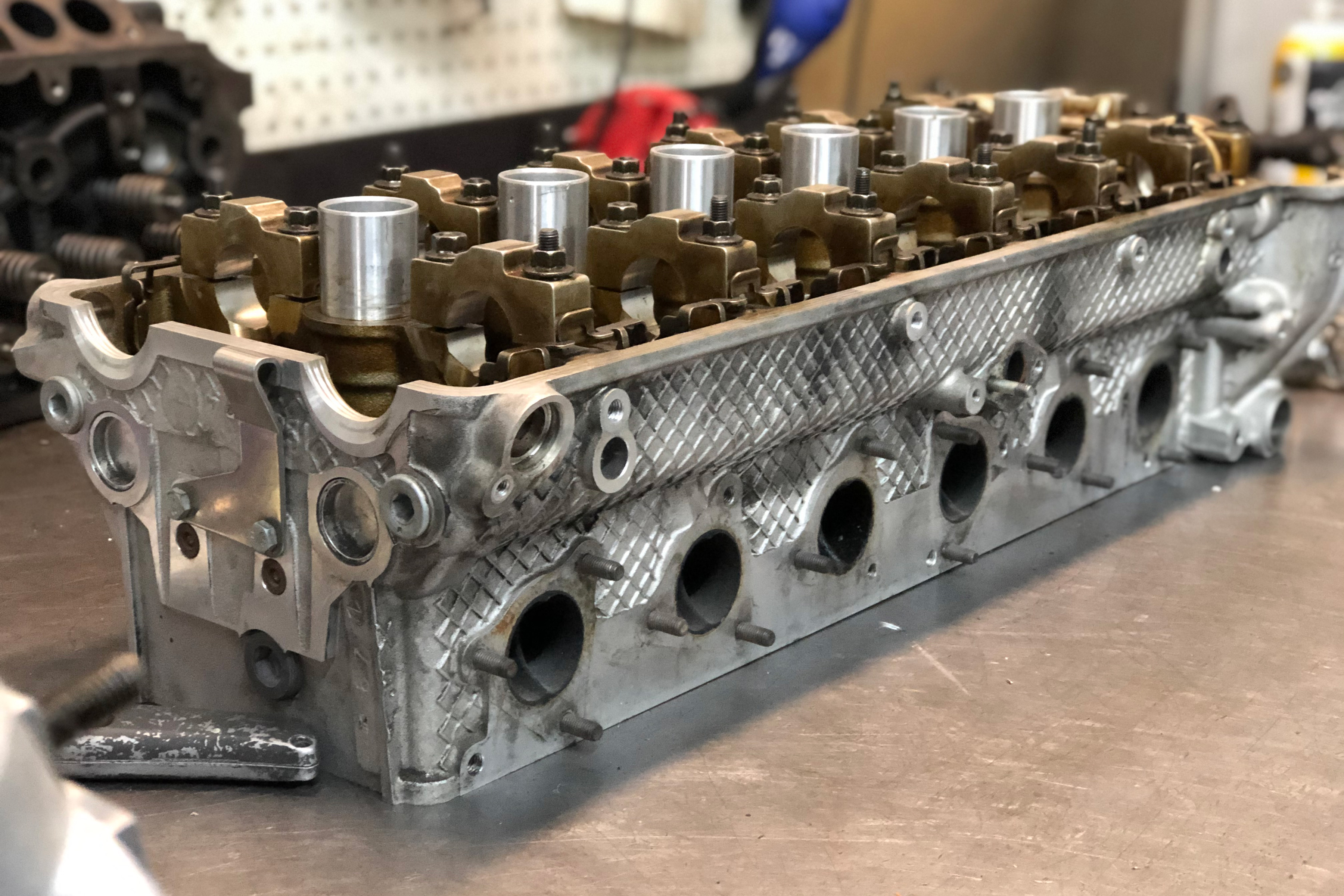
Having a specific output of 104 horsepower-per-liter and a stratospheric 8,000-rpm redline was unheard of outside of mid-engined Italian two-seaters or Japanese two-wheelers. The real beauty of this engine is apparent when you tear this beast apart. CNC-profiled intake runners, CNC-milled combustion chambers, large alloy valves, bronze valve guides, and a clean-dense solid alloy casting all seem more at home on a race engine than something that came off of the production line.
This feature list reads like a fantasy to most traditional canyon-carving, Ultimate Driving Machine purists. Fortunately, for the rest of us, the aftermarket feeds a need for those of us that love boost. Drifters, drag racers, and time attack junkies rejoice in big single-turbo kits or centrifugal-blower glory. The real beauty of engine modification is the reward you reap, when these high-volumetric-efficiency mills receive the unnatural aspiration and appropriate supporting modifications. This piece will guide you, ultimate power fiends, through the process of preparing the top end for big power on boost.
Looking Ahead to Save Headaches
Initially, we’re going to disassemble and inspect our core casting. An ounce of prevention is a pound of cure here. Putting this kind of time and money into a casting that isn’t viable would be a monumental mistake. While the S54 doesn’t have a reputation for cracks, taking the time to clean, visually inspect, and pressure test the water jackets is a worthy exercise.
What you don’t know can hurt you and your wallet. It’s extremely important to fully test your cylinder head casting to make sure it’s suitable for getting the expensive, intensive work ahead.
Shopping List
Once you’re able to call the core viable, it’s time to assess your goals. This build involves an E36-chassis drift car, utilizing a stock BMW short-block, all fed by a centrifugal Rotrex supercharger. The use of the stock short-block creates a small conundrum as the original piston isn’t relieved enough for full VVT operation when there are larger valves utilized on the intake side.
For this build we chose OEM size (35mm) nitrided stainless intake valves and 31.5mm (1mm oversize) Inconel exhaust valves; both in the single keeper groove conversion variety. Both the larger VAC Motorsports-sourced Schrick “Forced Induction” camshafts and the likelihood of rev limiter-kissing in the skid racer necessitates proper valve control. A durable set of dual high-rate valvesprings from Supertech Performance along with matching featherweight titanium retainers were used.
The S54 uses a unique-for-BMW, finger-follower rocker arm mounted on a rocker shaft. This provides valve opening acceleration and rocker ratio multiplication, but, according to some, can be a problematic wear item. We’ve seen success in using WPC Treatment on OEM rocker followers, though some may opt for a DLC coating.
Welcome to the Machine Shop
With the parts laid out, we can now approach the list of procedures we’ll cover in the machine shop. Even though the intake runner of the S54 is completely CNC-profiled, there are small areas for improvement, such as seat profile and pocket-throat diameter. The exhaust port is a high-velocity, divided, D-shaped venturi, meant for scavenging naturally aspirated, high-RPM spent gases. Profile work, such as straightening the runner, will have gains here. The usual mechanical interface of valve to guide still applies for heat transfer, valve sealing, and longevity. The S54s valve guides should be addressed as needed.
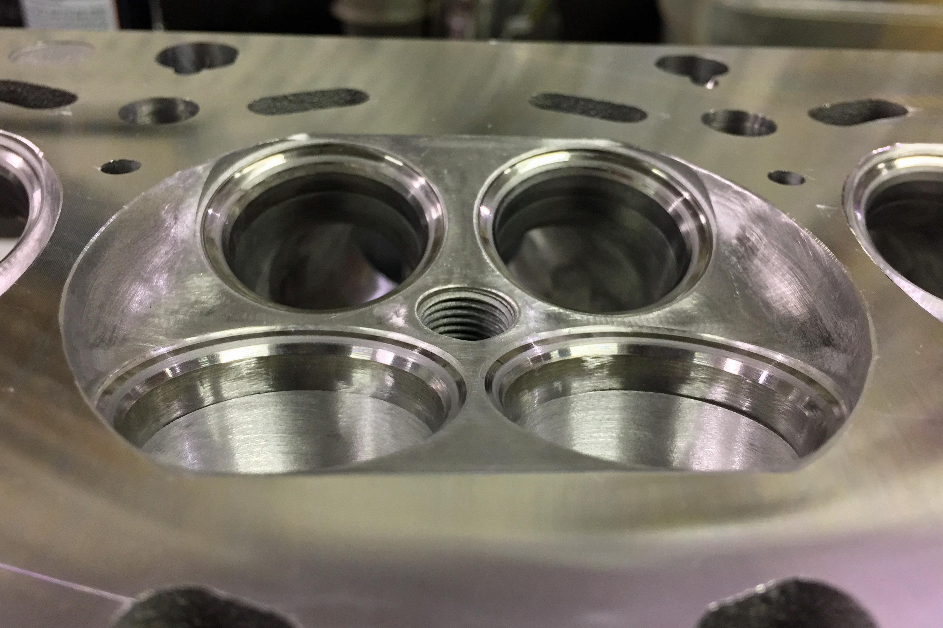
After port profiling and dressing, we look to simply smooth the combustion chambers’ sharp tooling marks. We also verify volumetric uniformity with a burette. Great attention is to be paid to seat profiling, given the increase in valve size on the exhaust. The valve seat serves two integral purposes: to sink heat out of the valve into the water jacket, and provide the port transition to feed the combustion chamber our valuable compressed (and often intercooled) atmosphere.
The seat profiling can be followed up with hand lapping to assure a properly mated seat-to-valve interface. Once the valve job is inspected and tested, the next step is deck-milling and flange inspection where the rotary PCD curls “sixes and nines” for an ultra-smooth and flat finish. A final part inspection happens at this point before hitting the parts washer. Once we have clean and appropriate parts, we bench-adjust the valves. We adhere to the cam manufacturer’s specifications and conclude final assembly with a final inspection.
Port Profiling
Before we cut a single chip, we need to lay-out and measure all of our objectives. Intake and exhaust valve sizes are 35mm and 31.5mm respectively. Our intake goal is at least 85-percent of that 35mm — or at least a 29.75mm throat diameter in the pocket between the seat and the port. The exhaust target is closer to 90-percent of 31.5mm — or 28.35mm — throat diameter.
Many may notice a trend of attention paid to the exhaust in this application; let this emphasize its importance to volumetric efficiency. Keep in mind that the engineers in Munich spent most of their time on the intake. We mounted the cylinder head in a Serdi valve seat machine and used a convex-radius insert to find the rough throat diameter. We need this measurement before we port the runners. It provides us the ability to hand blend the machining marks or seams left by the rotary throat insert as well.
An exploratory seat cut helps layout the throat pocket. While the perfect size throat is still debatable, there is no debate that improving its ratio is a key factor in improving overall flow.
The next stage requires no layout fluid or scribing. The intake ports are laid out with an O-ring groove and the exhaust would simply be cartoonishly large to scribe and port match. Thus, experience and discretion are two skills that temper the steady-handed die-grinder.
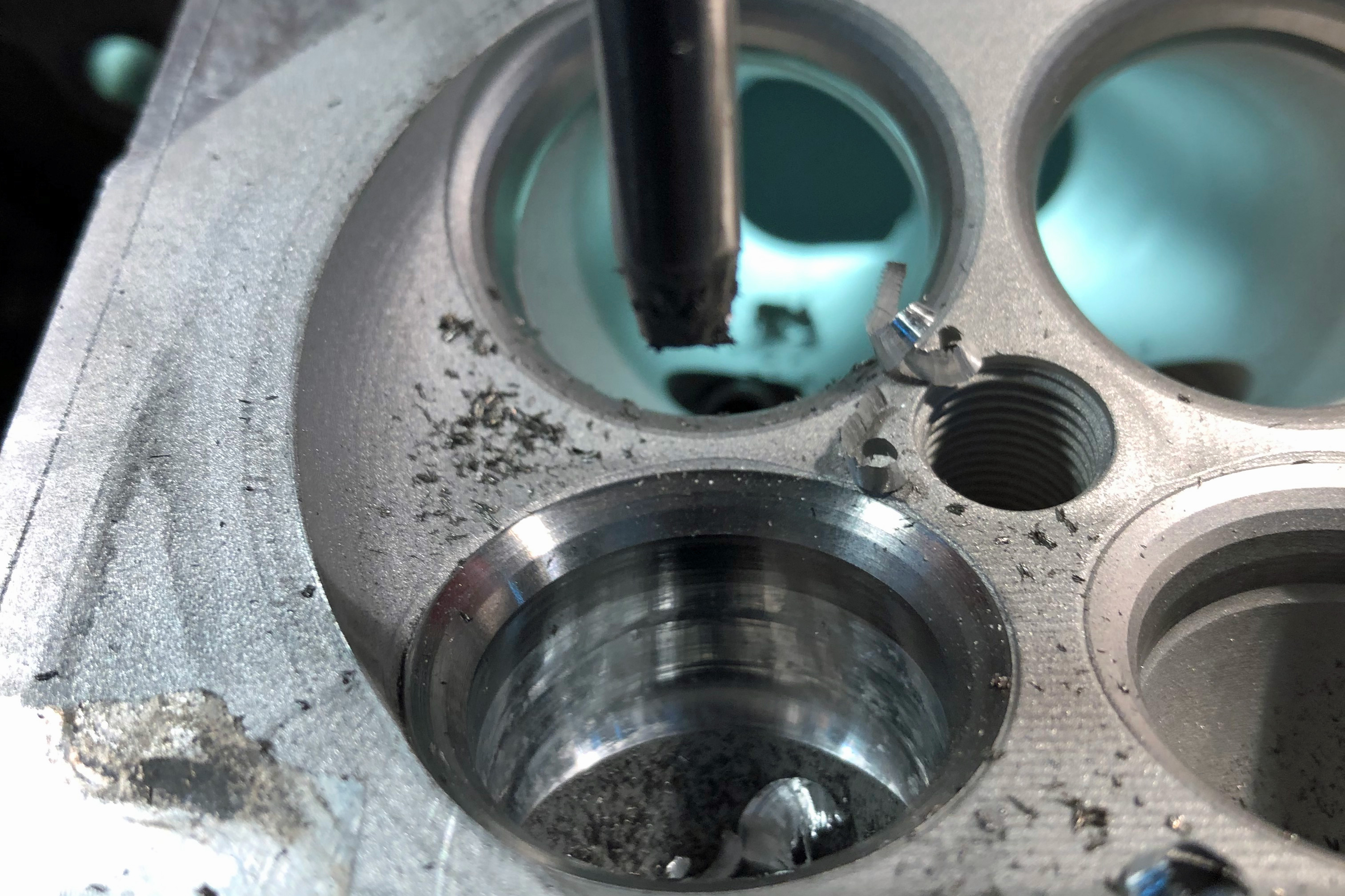
The largest areas of chip-making are the D-shaped half-moons of the exhaust port. We grind, straighten, and exaggerate the D shape. No more than approximately 2mm of material removal from the port walls should be ample for most applications less extreme than 1,100 whp. The sharp edges and dividers in the intake receive smoothing and bull-nosing with a simple 80-grit cartridge roll.
Once profiled, the exhaust receives 80-grit followed by 120-grit. We follow up with some light cross-buffing to knock down the texture for carbon control. The combustion chamber receives the same finish-massaging as the exhaust, knocking down high spots and tooling burrs to prevent any pre-ignition or glow-plugging.
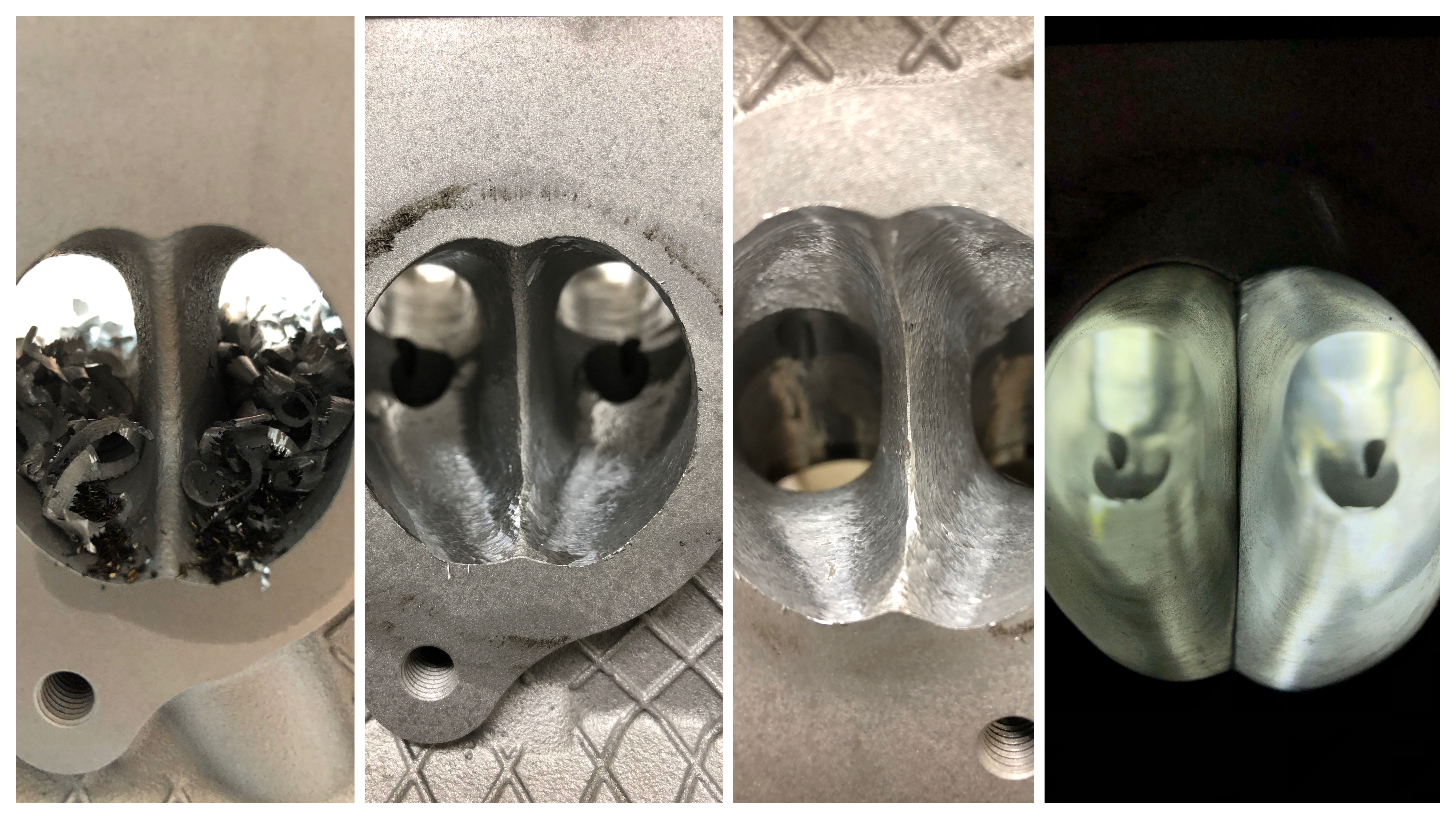
The progression of the exhaust port from chippy to slippery. The exhaust port gets the most material removal and reshaping work on an S54 head destined to see boost.
Please Be Seated
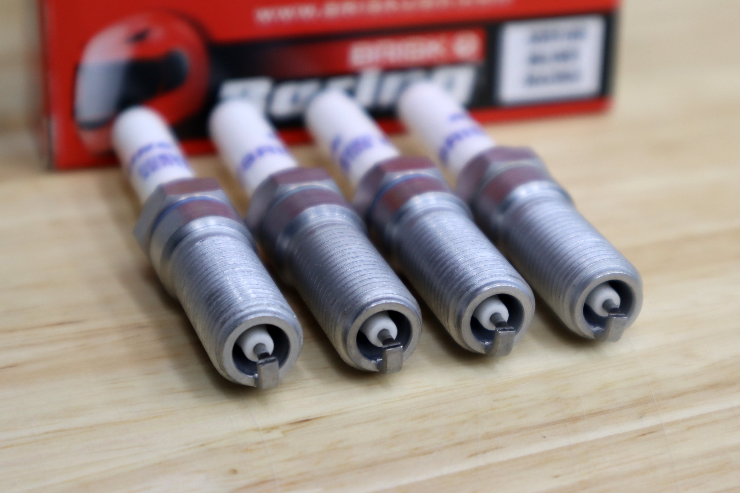
Profiling the valve seats is another process many consider a “dark art.” It is truly nothing more than physics and geometry. The S54’s compact 33cc combustion chamber utilizes a 12mm spark plug commonly found in motorcycles to fit the aforementioned valves.
In sticking with the compact, yet high-airflow theme, we opted for both 5-angle and radiused-seat cutters, available from Goodson Machine supply. Both cutters supplied us with a performance-friendly 1mm, 45-degree seat, mated to well-transitioned cuts, in and out of the bowl.
The Serdi 60 makes plain work of exotic angles.
If you’re using titanium valves or running extremely high horsepower levels, you should consider a copper alloyed seat like Moldstar90 or similar (beware of carcinogenic, beryllium alloys). We complete QC with a hand-lap job, using the old fashioned, fine clover compound to check our interference ring. It also provides a nicely broken-in valve face to avoid larger break-in changes in the valve lash.
These procedures only excel with round and appropriately clearanced valve guides. This is addressed on an as-needed basis, typically from very high-mileage and poor maintenance cores. A suitable replacement guide is a copper-manganese unit available from Supertech Performance. Remember, in this situation, concentricity is king.
Waiting to be lapped…hand-lapped.
Hitting the Deck
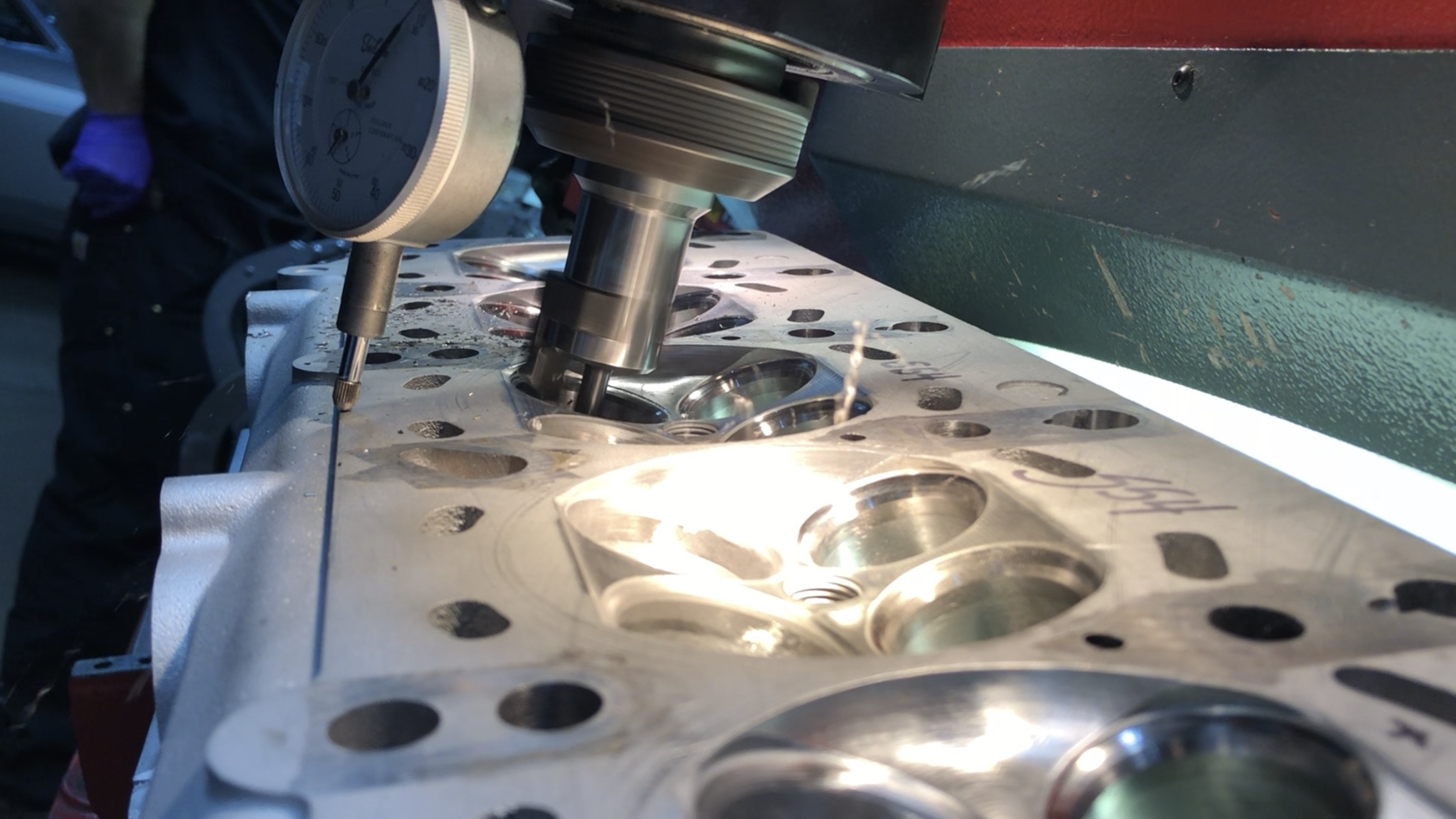
Without manifold flange fasteners in the way, we’re able to straight-edge and board profile the intake and exhaust manifold flanges by hand. It provides a smooth and flat mating-surface for a new gasket between the cylinder head and manifold. The cylinder head then gets jigged and precision leveled before we remove .002-.003 inch per-pass on the Rottler mill with a PCD insert. This leaves behind a smooth, MLS- or copper-head gasket friendly, mid-30s (Ra) finish. The chambers, port edges, and outside deck edges are deburred with a fat-flute rotary file before blowing the chips out.

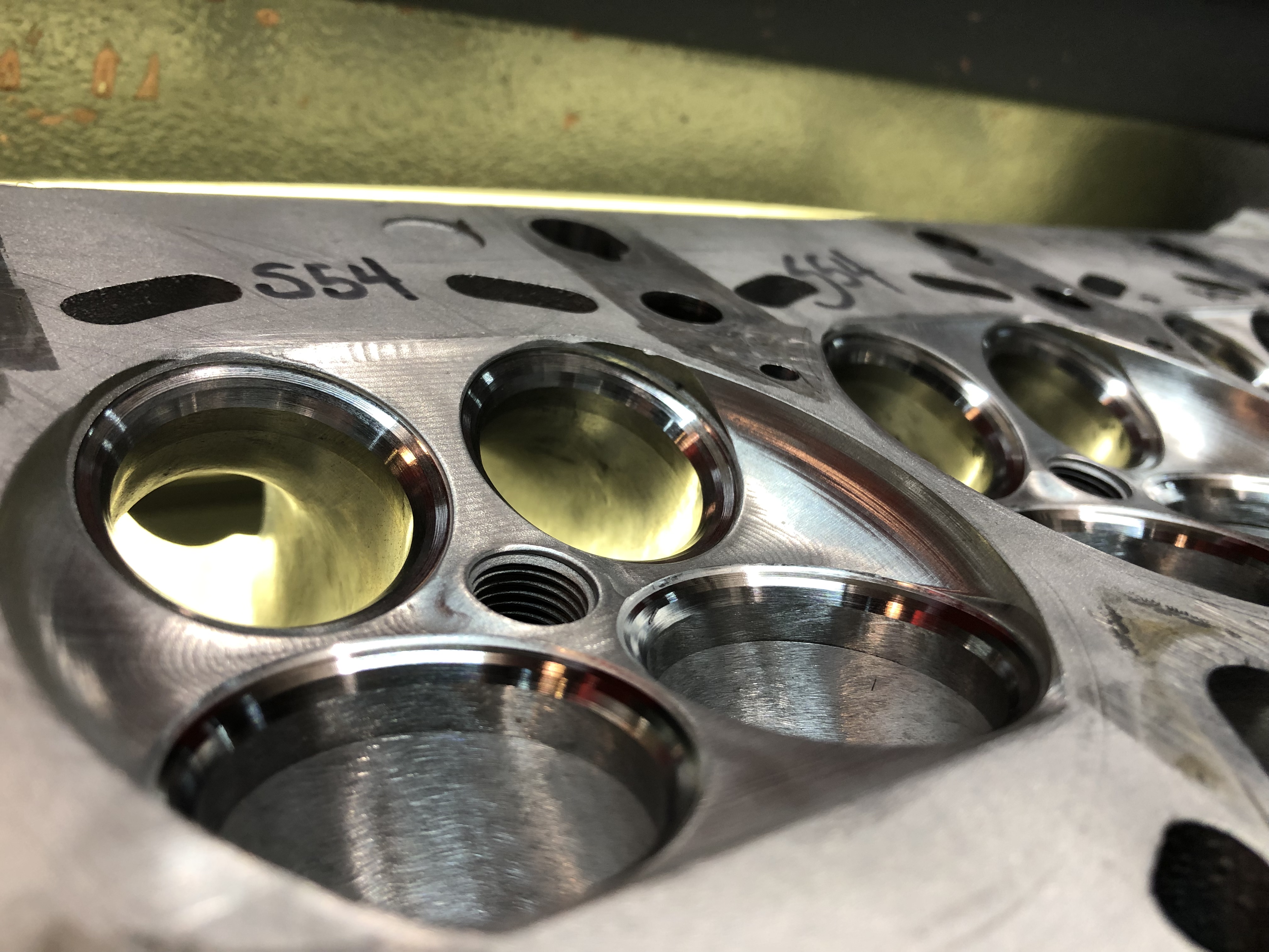
The Rottler surfacing machine with polycrystalline diamond tooling leaves a mirror-rainbow finish on the cylinder head surface.
Cleanliness is Next to Godliness
At this point, the chip-making is done and it’s time to wash away our toil and swarf. Brake clean or solvent — fed by a straw — and compressed air can remove pesky debris from tight locations. Once you feel safe about those tight locations, it’s time to run our shiny aluminum pieces through the parts washer.
Two types of machines provide the most effective cleaning: hot aqueous high-pressure spray cabinets or ultra-sonic submersion. In our case it’s the former whose operation resembles that of a giant dishwasher on steroids. Once scrubbed by a high-pressure, hot, and slightly caustic detergent, the casting components receive a rinse of water from an industrial hose and nozzle until the soap residue has vacated. These steps are followed by compressed air to dry any residual moisture.
A solid cleaning followed by a thorough visual inspection before mock-up is a critical step that shouldn’t be overlooked.
The Final Countdown
The S54 head is then taken to a clean assembly bench with a soft rubber table surface to protect the fine milling from scratching. This is where both a manual and experience keep us on the straight and narrow path of mise en place precision. We prefer to lay the valves, valve-spring seats, springs, retainers, and single-groove conversion locks arranged on the bench like rank formations on a battlefield. When everything is in its place, it’s easy to see what, if anything, is missing.

Here you can see the OEM-sized intake valves with their nitride coating, along with the 1mm oversized Inconel exhaust valves. The key to big gains on this particular application is getting the spent gasses out as quickly and as efficiently as possible.
Cylinder head mock-up for setting valve clearance is the next step; you may also adjust the valves on the engine if it suits you. We find it less nerve-wracking to dial the lash in before the commitment of a clamped head gasket. During this series of steps, we use lightweight checking springs in place of the high-rate dual springs for ease of mock-up. Remember that failure to adhere to the proper adjustment guidelines may net you burned valves, low power, a noisy valvetrain, or other embarrassing results.
Patience and a calm mind will suit you well during this phase.
Schrick Camshafts calls for a valve clearance of .25mm (.010 inch) intake and exhaust for use with their grinds. BMW calls for .18-.23mm (.007-.009 inch) and .28-.33mm (.011-.013 inch) clearance, on the intake and exhaust respectively. In fitting with the motorcycle theme, Wiseco makes an 8.9mm OD shim kit for Husqvarna, KTM, and Husaberg that also fits the S54: P/N: VSK4. You purists out there might be better suited to BMW P/N: 11340031525. If you (or your machinist) were on the ball during the seat cut, starting in the middle range on the shim thickness will work well for you.
Proper torque on the cam caps is critical for accurately setting valve lash. Doing this off of the engine can make life easier physically, and in case of encountering a problem, it doesn’t require you to remove the cylinder head from the block.
The valve stems receive Torco assembly lube on their stems and they are, again checked for consistency of fit as they are slid into the valve guides. Valvespring seats are loaded on the topside before springs and a pneumatic compressor leans into the titanium retainer. This happens 23 more times until all valves, springs, retainers, and locks are installed.
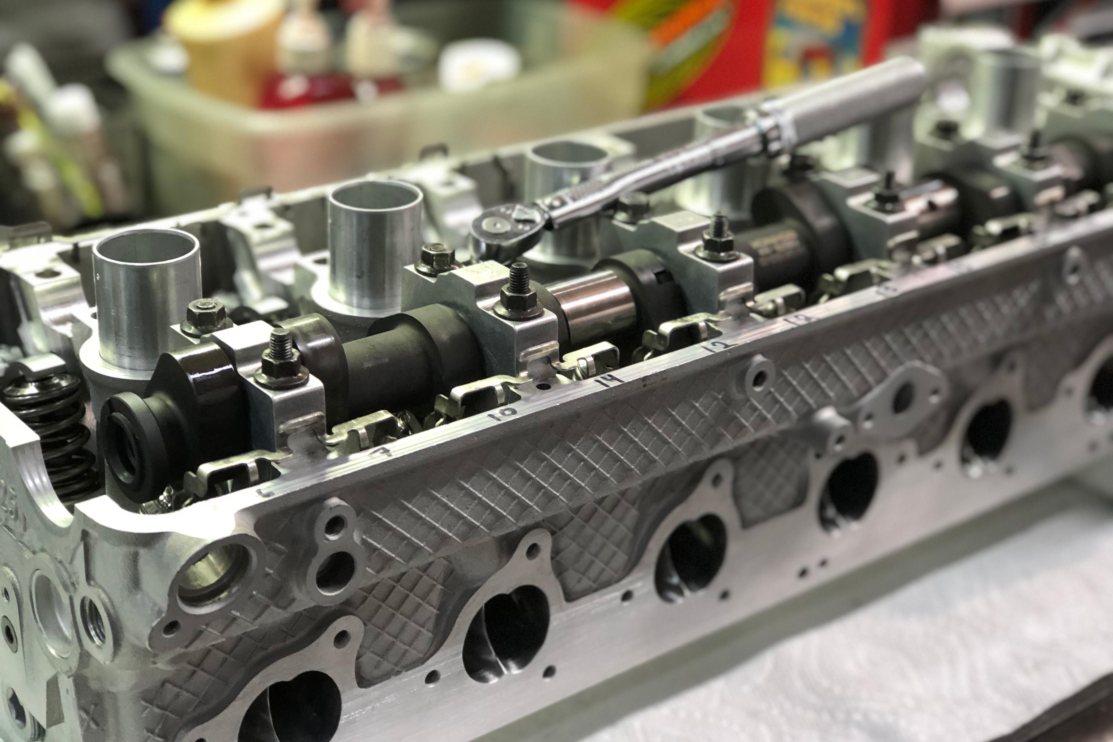
Rocker shaft installation is next, and it should be noted that on the S54, the exhaust rocker shaft has an oiling hole meant to be fed from the main oil gallery in the head. Failure to align that hole properly will result in a flat camshaft and followers. Finger followers are a point of contention for some that frequent the internet; I will avoid any contention by simply pointing out that there are three accepted styles of finger followers for use with larger camshafts and high-RPM operation: Schrick Performance DLC followers (P/N: SCH-CF-S54-DLC), DLC coated OEM BMW followers (P/N: 11337833259, contact Calico Coatings) or WPC treated OEM BMW followers (P/N: 11337833259, contact WPC Treatment).
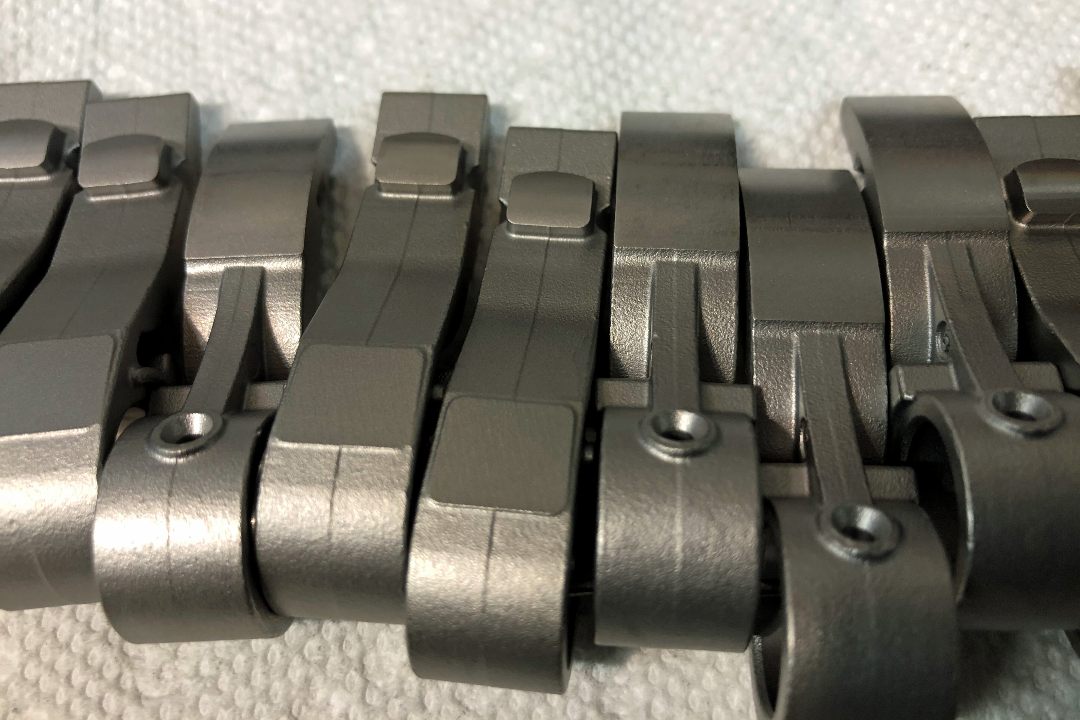
These WPC-treated finger followers are microtextured for oil retention and impregnated with WPC’s proprietary blend of surface-treatment metals.
Driven Lubricants makes an excellent, tacky camshaft and lifter grease; be sure to apply this liberally to the lobes and finger follower faces. Make sure to apply a lighter assembly lube to the camshaft bearing surfaces and journals before installing caps and nuts. The torque specs and order are up to you, because if you’re doing this, you should have a manual with that info.
Results May Vary
The arithmetic indicated that we would gain 2-2.5 psi back from the breathing modifications to the cylinder head. In preparation for the increased volumetric efficiency, we had larger six-rib main pulleys cut out of steel and then zinc coated for oxidation resistance.
In the end, the MAP sensor indicated a solid 3 psi increase, causing the Rotrex blower to peak between 14.5 and 17 psi, depending on the daily atmosphere. Trips to the Rotrex Impeller speed calculator indicated we might be slightly overdriving our C38-92 impeller. The breathing improvements coupled with the main pulley yielded gains of 156whp and 119 lb-ft of torque.
There are many horsepower gains to be realized in most production engines, even those deemed too complicated or expensive. The true art is in finding the threshold of diminishing returns in each system, before meeting that wall with invested time and money. I hope to return to this topic of airflow and forced induction in the context of modern inline sixes in the near future. When that time comes, it will be with even more data to share with you.
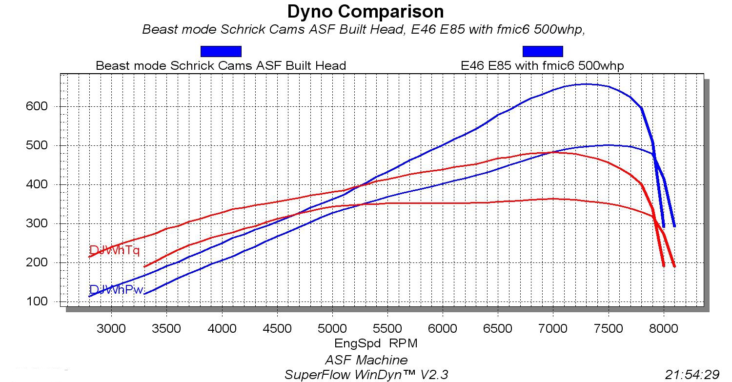
Better breathing brings bigger horses. That is a radically improved power curve for a little more boost and a lot more efficient cylinder head.