Tuning Holley carburetors isn’t difficult, but when it’s time to get into fine-tuning your street car, adjusting the fuel curve is a great path to travel. Holley engineers have created several tuning avenues through the modular design, to create a proper air-fuel ratio pattern for just about any engine. It all depends on how deeply you want to dive into the carburetor.
This month’s approach will offer even the most basic Holley tuner some ideas on how to make his or her engine make great power while running as efficiently as possible. But before we get into the fun part, let’s first run through how the main metering and the power enrichment circuits function. Once we know that, we can then figure out how to make it work better.
Putting the Horse Before the Cart
The main metering circuit flows fuel where there is a vacuum signal in the venturis. This signal is lower pressure, created by air rushing past the boosters (think back to high school and Bernoulli’s Principle). This vacuum signal allows atmospheric pressure pushing on the fuel in the float bowl to flow through the jets and then into the main well in the metering block. This is where precisely-drilled holes (called an emulsion circuit) mix air with the fuel. The fuel and air is pushed out of the main well and into the boosters where it enters the incoming air.
This entire system is calibrated by the main jets, the high-speed air bleeds, and the emulsion holes in the metering block. To differentiate between low and high load, Holley created what is called the power valve circuit. Once the throttle blades open sufficiently to drop the manifold pressure below a certain manifold vacuum point, the circuit opens and additional fuel is added to the main metering circuit.
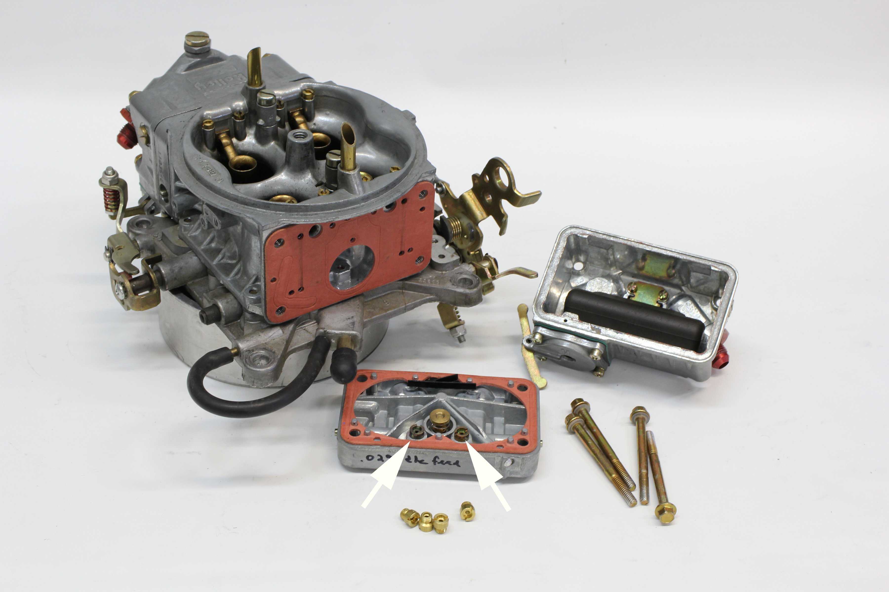
We’ve removed the primary fuel bowl and metering block from this 650 cfm Holley carb so you can see the individual components. The main jets are indicated by the arrows with the power valve located in the center.
Holley’s power valve is a simple, spring-loaded diaphragm valve that uses engine vacuum to pull the valve closed. Rated in inches of mercury (InHg), as an example, the most common rating is a 6.5. As the throttle opens, manifold vacuum drops from a high of around 16-18 InHg down to around 0.5 InHg at wide-open-throttle (WOT). A 6.5 InHg power valve would open anytime the manifold vacuum is lower than this value. Holley offers multiple power valves rated at points from 1.0 to 10.5 InHg.
Underneath the power valve in the main metering block are two precision-drilled holes called the power valve channel restrictors (PVCR). These restrictors are like a second pair of jets feeding fuel to the main metering well but only when the power valve opens. Most Holley carburetors allow easy changes to the main jets but use specific-drilled orifices for the PVCR. Later performance Holleys and most billet aluminum main metering blocks are now drilled and tapped for tiny, screw-in replaceable restrictors that make metering changes much easier. That’s what we will get into next.
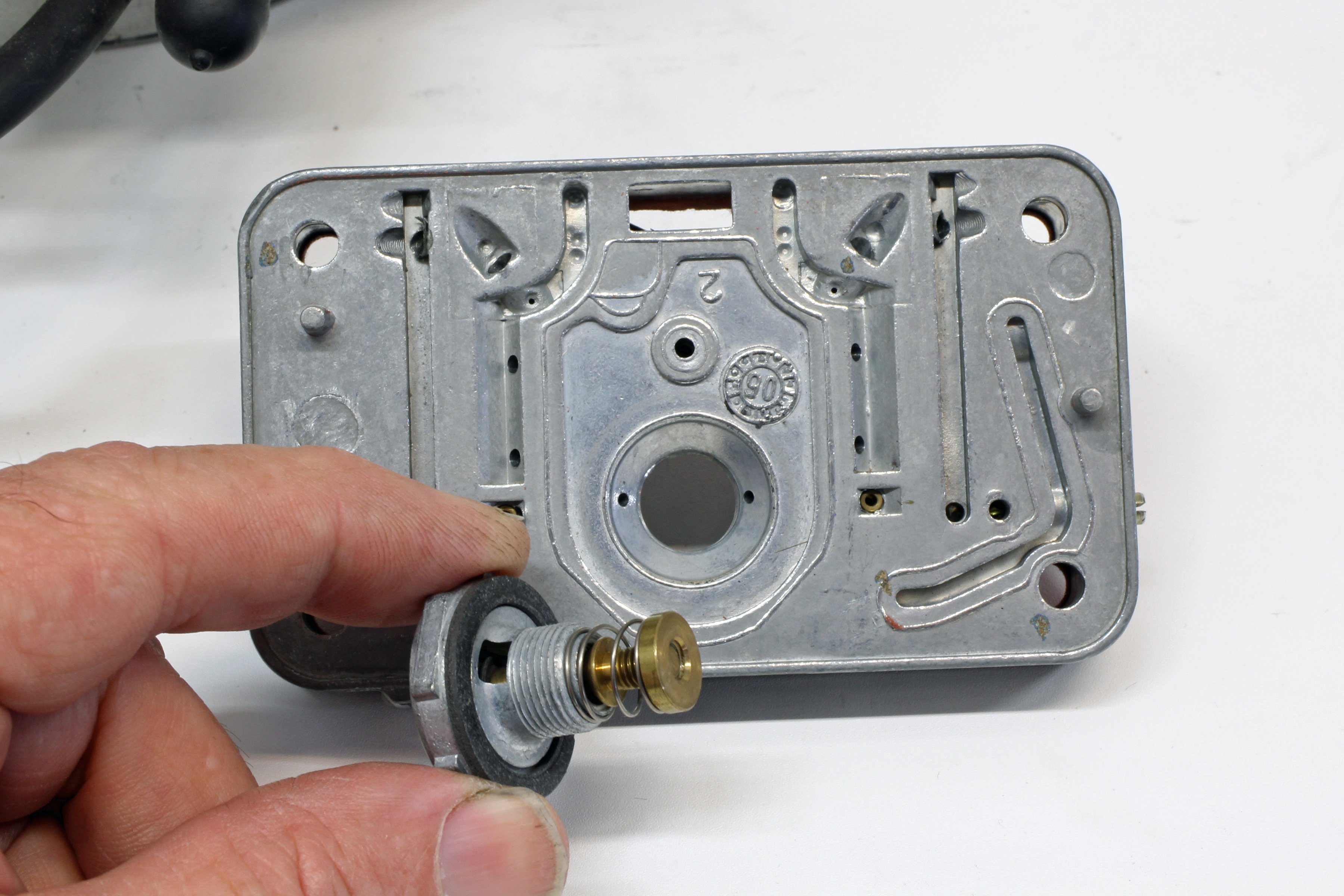
On the opposite side of the metering block is the power valve that screws into place using a large 1-inch box-end wrench. Always make sure the power valve gasket sits flush on the ledge of the power valve so it will seal properly.
The reason for the power valve system is to allow the tuner to use smaller primary main jets for part-throttle use to maintain a lean air-fuel ratio, which allows the engine to run more efficiently. Then, with heavier throttle opening (less than 6.5 InHg for example), the power valve opens and additional fuel is added to create the proper air-fuel ratio for max power.
The ratio of the amount of fuel added by the power valve will change with each version Holley carburetor, but typically the power valve circuit will add anywhere from five to eight jet sizes-worth of additional fuel. Power valve circuits are primarily used only on the primary side of the carburetor; most Holley four barrels (with some exceptions) do not use a power valve for the secondary side, relying instead on large secondary jets.
Newer power valves are laser etched with their rating (right) while older versions are stamped (left). These valves are rated at 3.5 inches of mercury (3.5 InHg).
Now Let’s Get To Tuning!
The first place to start power valve tuning is to choose when this valve should open. Choosing a lower manifold rating (like 4.5 InHg) delays the onset of additional fuel. This might work on a street car with a deep gear and a loose converter for example. Where the power valve opening point might be more critical is in a towing situation where a long climb up a steep grade would demand more fuel to ensure the engine does not run too lean. In this case, an 8.5 InHg power valve might be a better choice. Each situation and engine will require a specific tuning application.
If you are unsure as to where you think the power valve should open, the most common power valve opening point is what Holley uses as a starting point: the 6.5 InHg valve. This delays the opening of the power valve as long as possible to improve fuel mileage in an average application. If using this valve creates a mild sag or loss of power as the primary throttle is gradually opened, substituting a 7.5 or 8.5 InHg valve should solve the problem.
If you remove the metering block from a Holley carb from a running engine and the cavity behind the metering block is wet with fuel, this is strong evidence of either a leaking power valve or a bad gasket. This demands you check the power valve to see if it will hold vacuum.
A classic tuning myth that has managed to survive into the 21st Century is that you should never use a power valve opening point lower than your idle vacuum. The belief is that the power valve will open at idle and dump fuel into the engine, fouling plugs and making the engine run miserably. This is incorrect and illustrates a basic lack of knowledge about how this circuit works, because the power valve enrichment is not directly tied to the idle circuit.
The power valve circuit is connected to the main metering circuit. The main metering circuit directs fuel through the boosters and fuel flow only occurs with the throttle blades have opened far past idle. With the engine at idle, the power valve can open, but no additional fuel is delivered to the engine because there is no demand from the boosters.
A simple way to check a power valve to ensure that the diaphragm has not been damaged is to use the suction cup supplied with the Mightyvac vacuum pump. Wet the cup, apply vacuum, and see if the valve will hold vacuum. If the tool holds vacuum, the valve is good. If the vacuum drops off quickly, the diaphragm is ruptured and must be replaced. There are other ways to check the power valve, but we’ve found this to be the simplest.
The best approach is to use a power valve that opens as late as possible (the lower the rated number, the later the valve opens) to delay the addition of more fuel until the engine load demands it. Not only will each engine be different, even swapping from a dual-plane to a single-plane intake manifold is a guarantee the engine’s fuel demands will change.
The Domino Effect of Carb Tuning
For a street engine, one way to lean the part-throttle air-fuel ratio and improve throttle response would be to reduce the primary jet size slightly (assuming the primary circuit is a bit rich). However, this also reduces the amount of fuel delivered at WOT. So to compensate, if we reduce the primary jet by several steps (assuming the engine, in fact, prefers to run leaner at these smaller throttle openings) we can compensate for the loss of fuel at WOT by increasing the size of the PVCR. This requires some math, but we promise to keep it really simple.
Holley jet sizes are marked with what most enthusiasts assume is their drilled orifice diameter. While the numerical jet size is sometimes close, the number marked on the jet is not always a match for the drill size. That’s because Holley rates its jets by flow and flow is affected by the entry angle. So it’s possible to have two different jet sizes with the same orifice diameter. This is due to their differing entry angles, which ultimately affects their final flow rate.
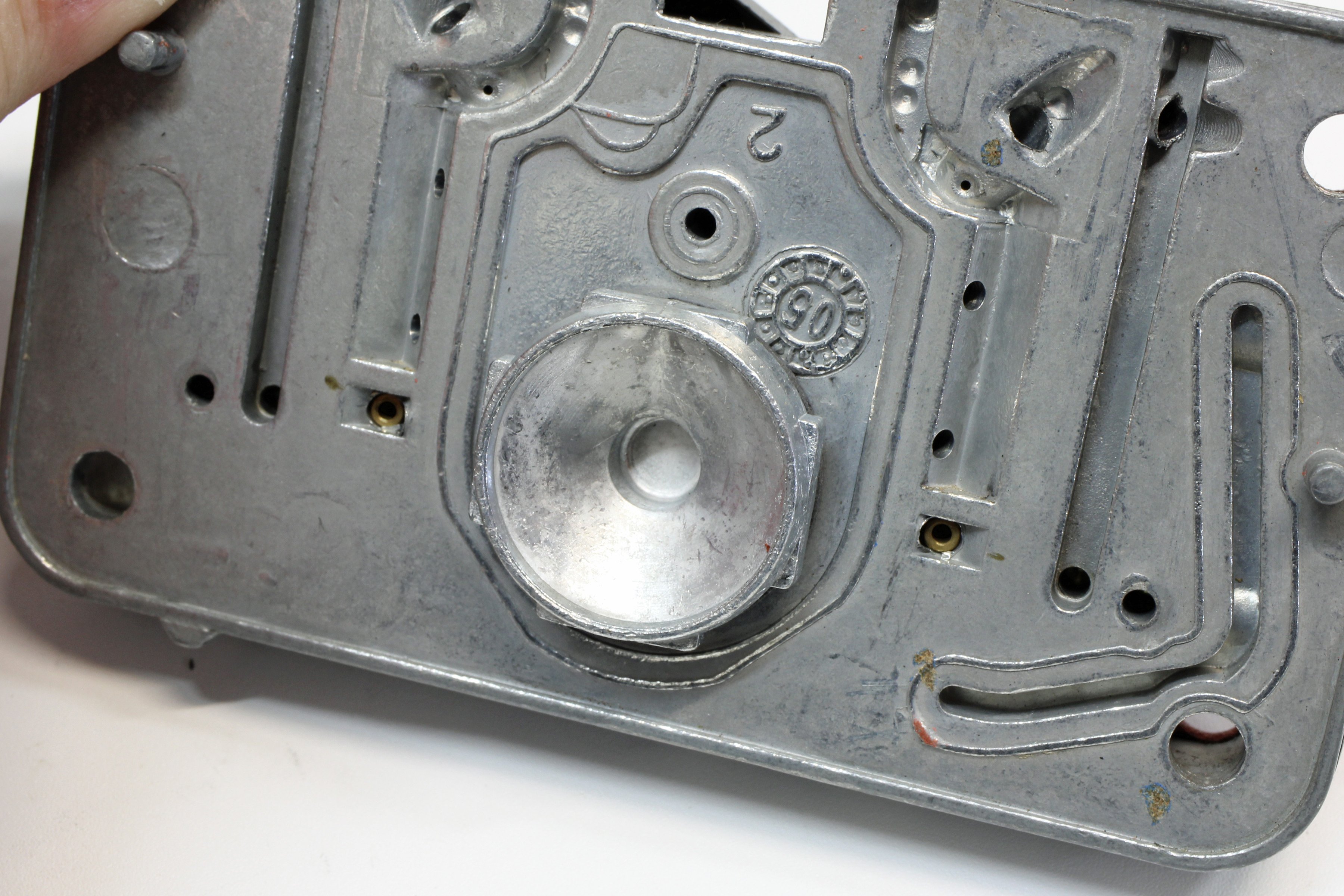
This metering block has drilled PVCR holes – in this case for the 750 cfm Holley uses 0.062-inch PVCR’s. This restriction can be enlarged by drilling out the holes or reduced by filling them with epoxy and drilling smaller holes. Both modifications are semi-permanent and time-consuming.
For simplicity’s sake, we are going to assume flow dimensions for both the main metering jets and the PVCR will be based on their orifice size. For this example, we’re going to use a mechanical secondary 650 cfm Holley. The Holley 650 (P/N: 0-4777-9) carb is factory jetted on the primary side with 67 main jets and a power valve with a 0.038-inch PVCR.
The secondary side of this carb does not use a power valve to balance the fuel flow between the primary and secondary, so it uses 6-step larger 73 jets. To determine the overall fuel flow capacity of this system, we must first calculate the total flow area for the primary side.
The first step is to calculate the jet flow area. Our accompanying chart shows a Holley 67 jet uses a 0.0663-inch diameter orifice which equals a flow area of 0.00353 square inches. This is established by using the formula for the area of a circle (Pi times the radius squared).
Primary 67 jet area = 0.00353 square inches
Secondary 73 jet area = 0.00418 square inches (17-percent larger than primary side)
Primary PVCR diameter is 0.038-inch = 0.00113 square inches of area
When we add the PVCR area to the primary jet area – this equals 0.00466. This is 11-percent richer than the secondary side. For the record, we are only calculating one venturi’s flow area on the primary and secondary sides. For total flow area, we would double these numbers, but for this example, we’ll deal with just one set of numbers.
Let’s say we want to improve fuel economy by cutting the primary side by two jet sizes but we still want to maintain the same overall WOT fuel flow. We can do this one of two ways. The easiest way is to merely increase the secondary jetting by two sizes.
Holley Jet Chart
| JET SIZE (NUMBER) | ORIFICE SIZE (INCHES) |
| 65 | 0.065 |
| 67 | 0.0663 |
| 68 | 0.0685 |
| 70 | 0.0735 |
| 72 | 0.0755 |
| 74 | 0.080 |
| 76 | 0.084 |
| 78 | 0.087 |
| 80 | 0.089 |
This information is taken directly from the Holley catalog. A 76 primary jet offers a diameter of 0.0840-inch. We measured 10 new Holley jets of that size and found diameters ranged from 0.082 to 0.083-inch. But the entry angle affects flow as well as orifice size. Holley says its jets are sized by flow and not by orifice diameter so that’s the reason for the disparity. The generally accepted range is a two- to three-percent change in flow per jet size. Most tuners will perform jet changes in increments of two, from 76 to 78 for example.
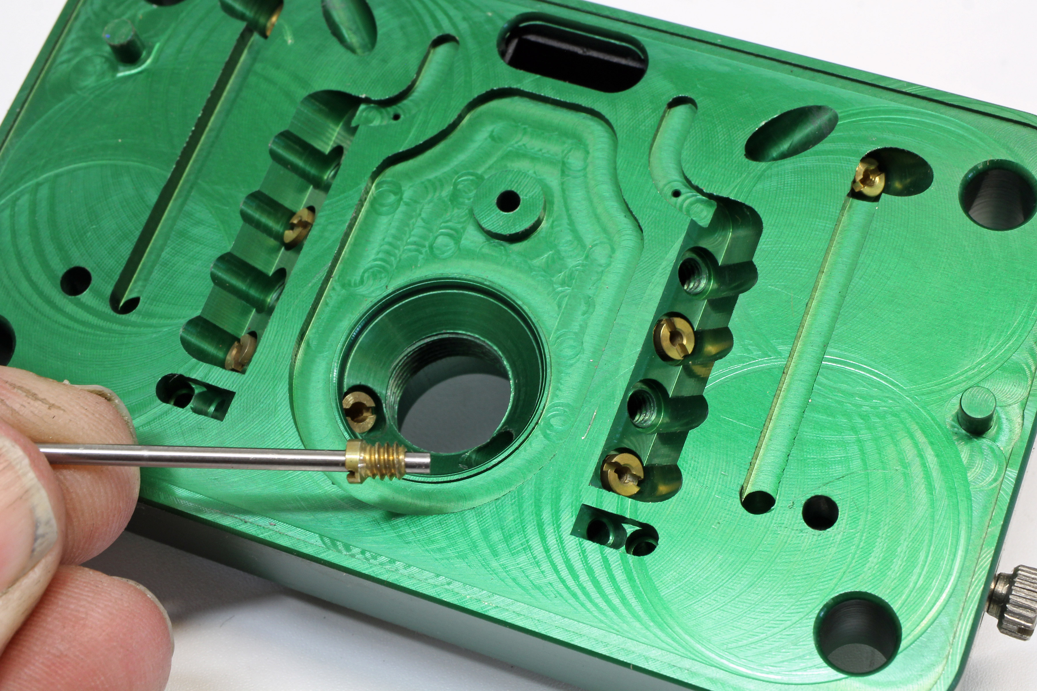
Billet metering blocks, available through Holley and other sources, offer small screw-in bleeds that make changes much easier and quicker. But this does require having a stock of bleeds on hand, should a change be desired. This particular green metering block is from Quick Fuel, intended for use with E85 fuel.
From the factory, Holley has designed the carburetor with slightly more fuel delivered on the primary side compared to the secondary, so since the primary side is already slightly richer than the flow from the secondary side, this might help balance the overall fuel delivery front to rear.
It’s also possible that we might need a little more fuel on the primary side when operating at a load where the primary is more than half open but the secondary is still closed. It’s possible the engine could run lean in this situation. We can increase the size of the PVCR restrictors to compensate for reducing the primary jet size. Here’s how we do that.
We know we need to increase the diameter of the PVCR, but even a small diameter change can make a big difference in area. So we tried a 0.003-inch increase in diameter to 0.041-inch. This produced an area of 0.00132-inch. By subtracting the area of the 65 jet from the area of the larger 67 jet, this reduced the jet area by 0.00134-inch – so our 0.041 PVCR is only 2-percent less. But a 0.042-inch PVCR would excessively overshot the area increase with a new area of .00139 sq. in., so we opted for the 0.041-inch PVCR.
There is a limit to increasing fuel flow from jetting and increasing the size of the PVCRs since the channel leading to the boosters is only so large. This particular carburetor measured 0.155-inch. Once the flow area of the jets and PVCR approaches the flow area of this main channel, further jet increases will be ineffectual, but this really only occurs when dealing with alcohol fuels like E85.
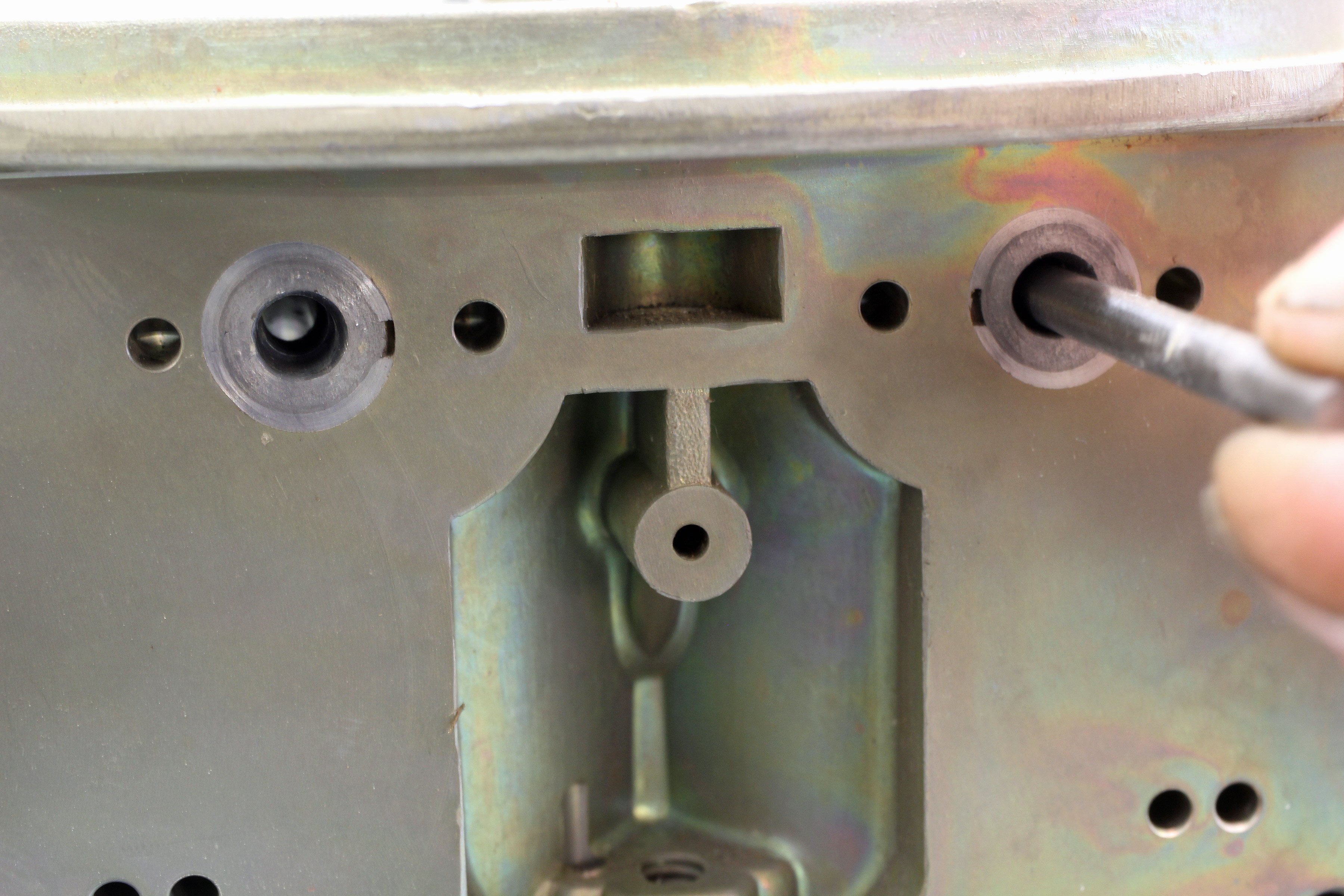
The ideal situation for carb tuning is a billet metering block with screw-in bleeds. Once the proper bleed is selected, it’s a simple matter to screw in the appropriate size and the task is finished. In the case of a metering block with drilled PVCR holes, we can increase the diameter of these holes with a 0.041-inch pin vise drill bit.
This process is not difficult but as you can see, it does require a little bit of math. By balancing these orifices, you can create a custom-tuned carburetor to the engine’s specific needs and make it more efficient as well. Big carburetors don’t have to necessarily deliver poor fuel mileage if you know how to make use of these simple tuning procedures.
Most Holley carbs are fitted with no power valve in the secondary metering block. However, some carburetors may be fitted with a secondary power valve which can be used if additional fuel is demanded on the secondary side. If not, the power valve opening can be blocked with this simple block-off plug from Holley (P/N: 26-36).