
In the movie Jaws, the sheriff is tossing chum in the water and comes face-to-face with the giant shark. He backs dramatically into the wheelhouse and proclaims “We’re gonna need a bigger boat.”
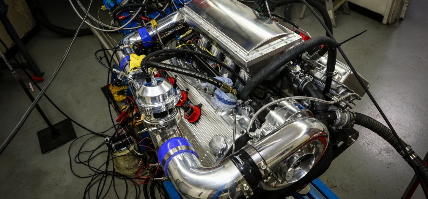
Our friend Mark Gearhart recently built a thumpin’ YSi-B Vortech-supercharged Coyote, and during a recent dyno test at Westech the engine twisted its way to nearly 1,200 horsepower on E85 fuel. When the discussion eventually moved to stuffing this beast into a street car, the consensus opinion was “We’re gonna need a bigger fuel pump!”
Four-digit power is now all the rage. There are many who insist you have to be packin’ a blower or turbo and pushing this kind of power just to be noticed. While the big numbers are impressive, they also place great stress on support systems—like fuel delivery. We decided to investigate what it takes to properly feed one of these monsters.
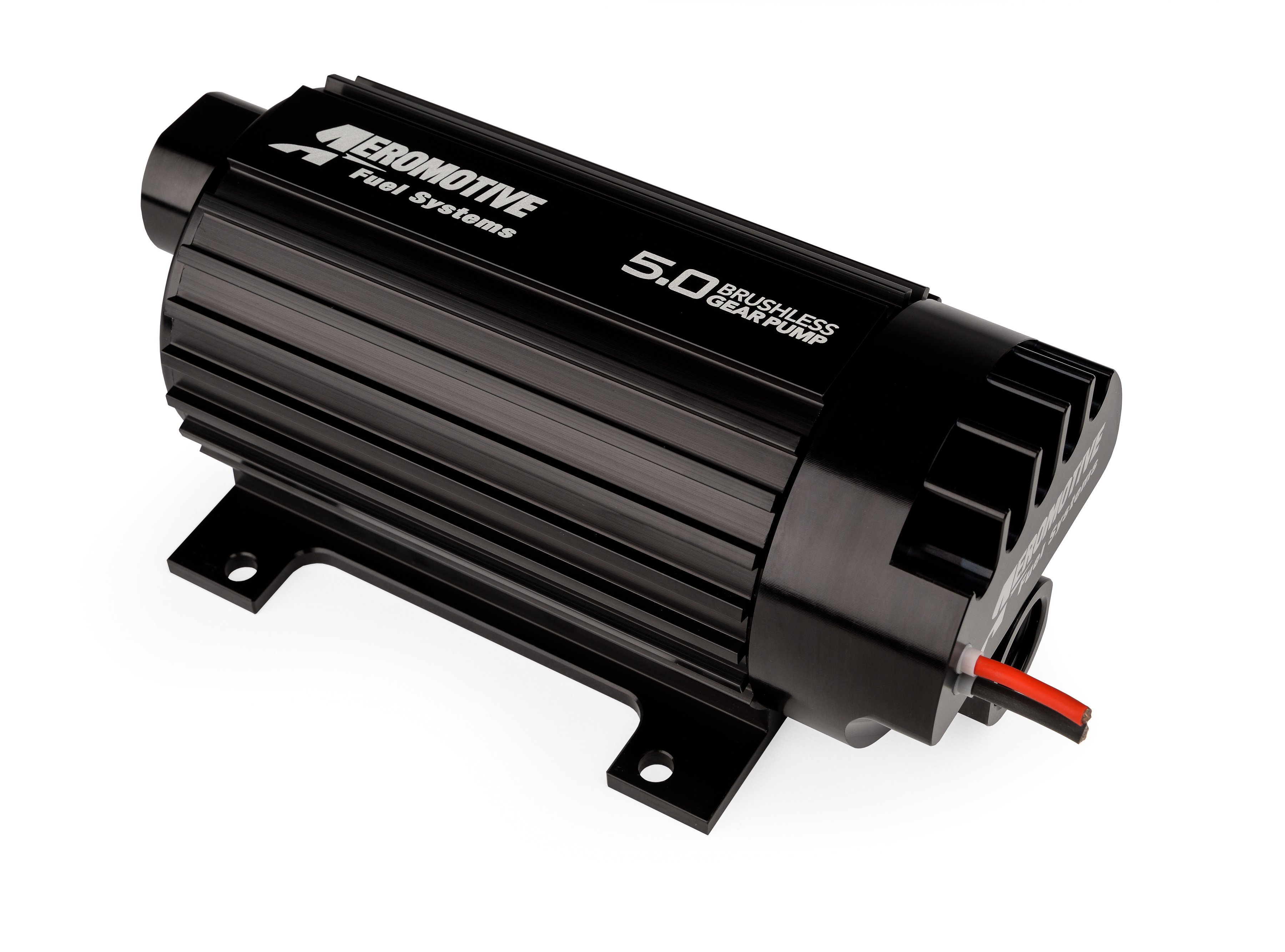
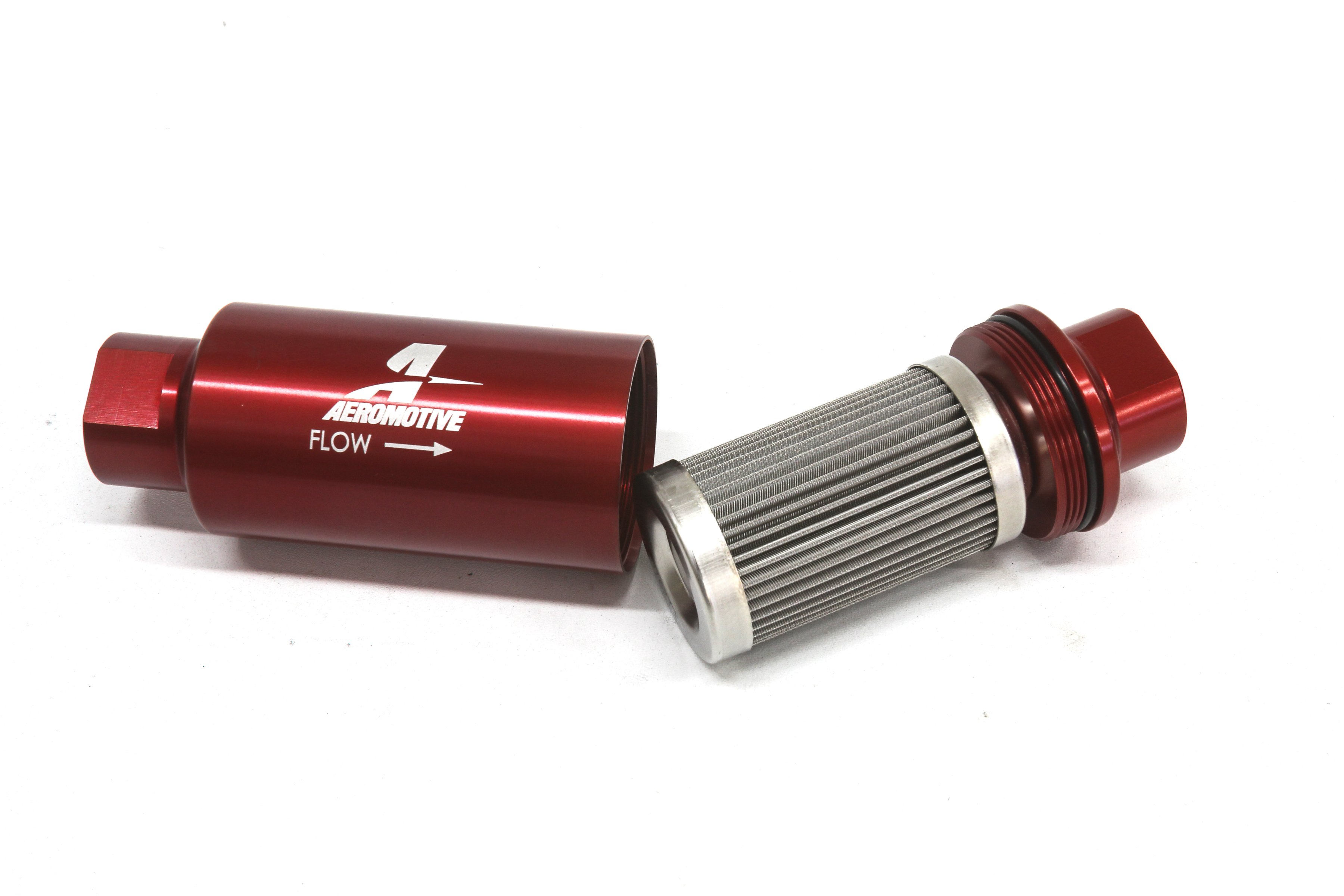
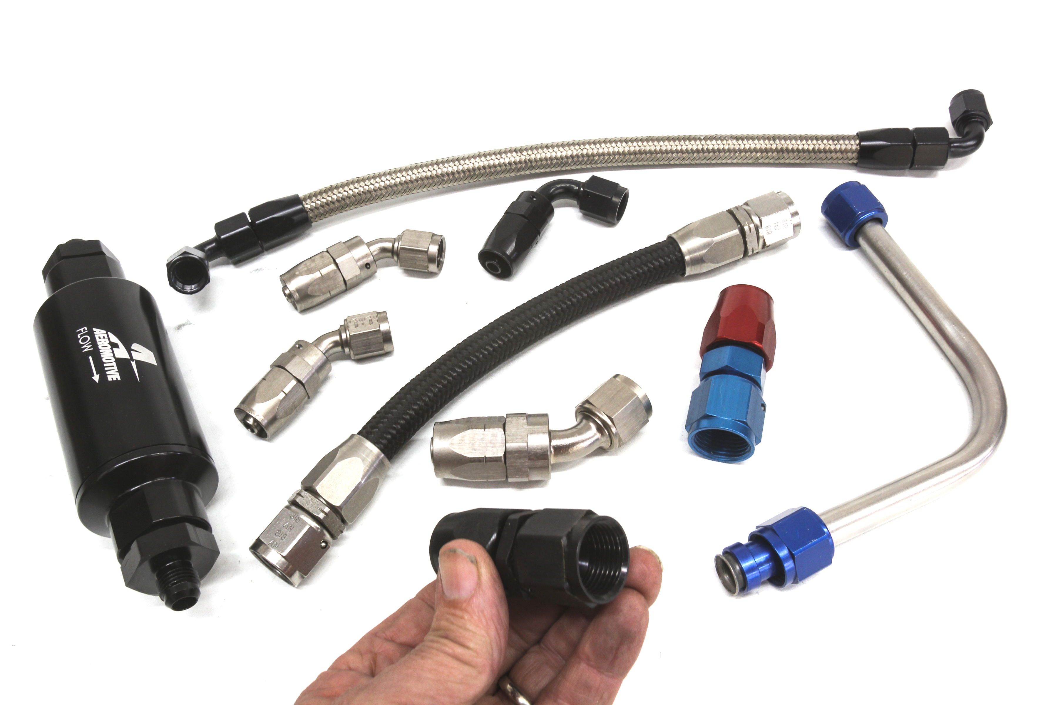
(Left) With over 1,000 pounds-per-hour of fuel supply available at high pressure, Aeromotive’s new Brushless Gear pumps are capable of not only increased flow for an electric inline pump but also higher pressure capability as well. The brushless design draws less current combined with improved durability. (Right) High-capacity systems demand an equally high-flow fuel filter. Small filter areas can quickly clog up and reduce flow and potentially kill a fuel pump due to the restriction. Large filters offer abundant area to pull out debris while not restricting flow.
Doing The Math
We punched the keys on our calculator and stumbled through the math to determine how much liquid Jack Daniels this engine would guzzle at max horsepower. But before we get into the details, let’s cover a few facts that are often overlooked.
First and foremost, it’s important to emphasize that the fuel delivery system must be viewed as a system. Unfortunately most builders approach this as merely a pile of individual parts. That tends to work with low delivery rates and 400 horsepower. But with engines making four-digit power, you can no longer enjoy the luxury of overlooking details. The entire system—including the fuel injectors—must be considered as members of the same team.
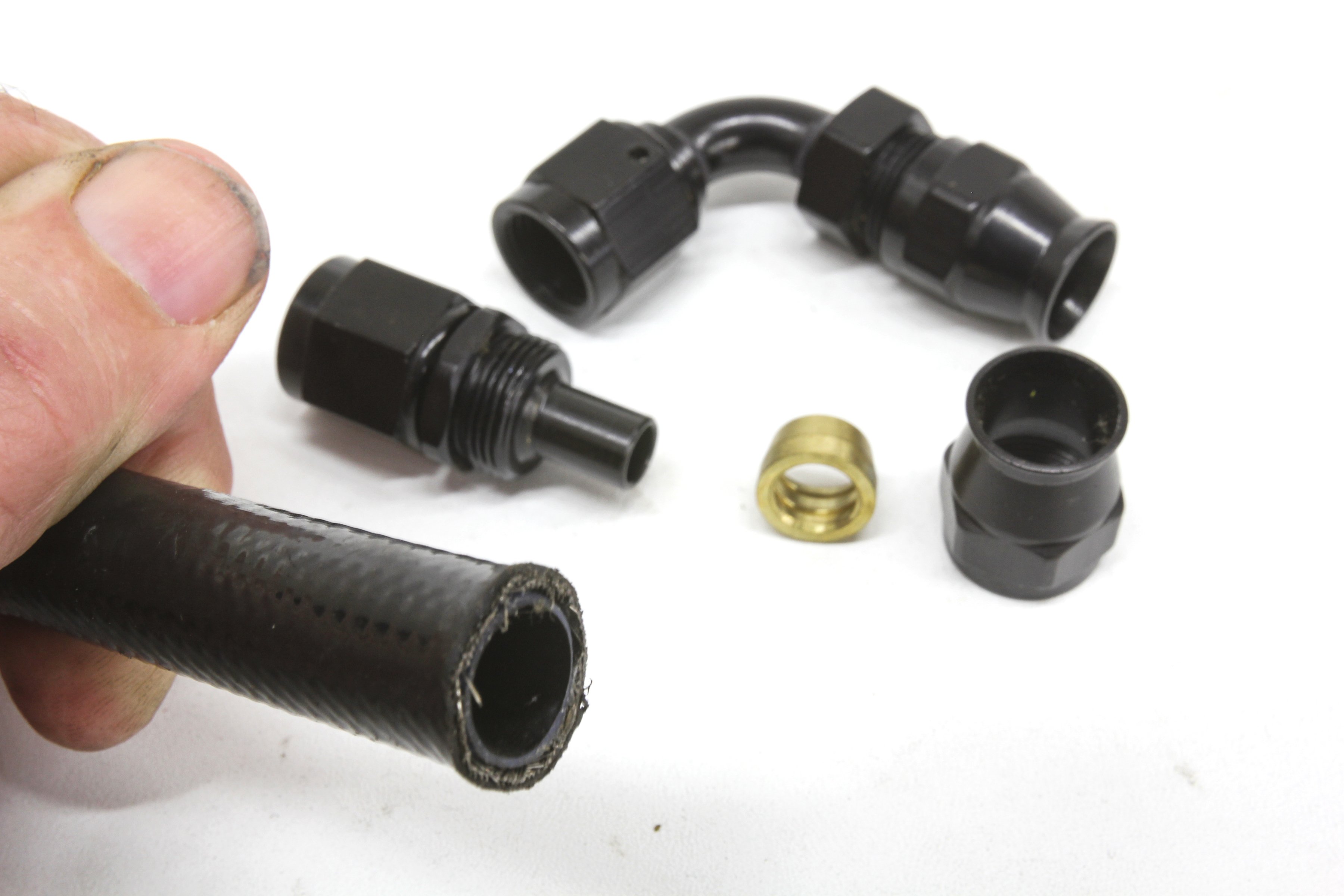

(Left) When considering a PTFE fuel line, always look for a carbon-impregnated line. High flow rates through a non-conductive (white) PTFE line will create static electricity that eventually perforates the line (creating a leak) in search of an electrical ground. This is a carbon-impregnated, smooth-bore PTFE line from TechAFX. (Right) While convoluted fuel line like this PTFE hose (left) allows easy handling, the undulations can reduce its flow rate. These are both -6 lines but obviously the convoluted line offers a slightly larger inside diameter as compensation. A smooth bore hose (right) will offer dramatically better flow rate but must be handled carefully to prevent kinking.
Naturally-aspirated, carbureted engines are the easiest to feed, because they push fuel at perhaps 15 psi to a dead-head regulator that knocks that down 5 to 7 psi. Any pump designer will tell you that pressure and volume are inversely proportional, which means as the pressure requirements increase, the volume available from that pump is reduced. This makes the EFI systems a bit more challenging with base (starting) fuel pressures from 43 to 58 psi and beyond.
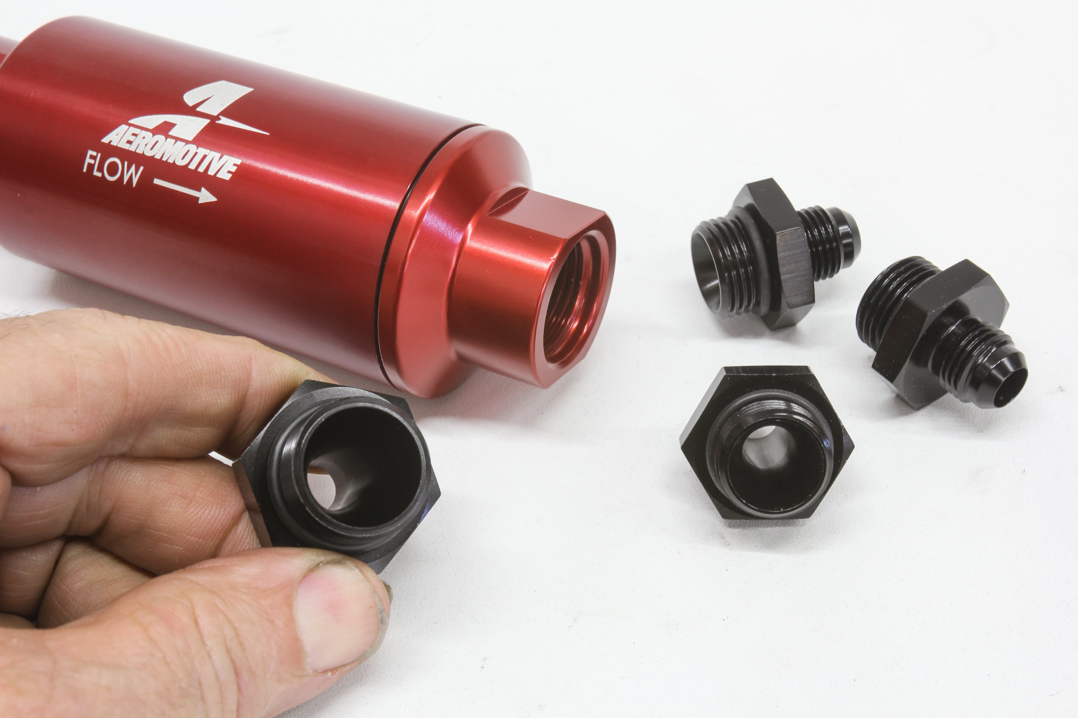

(Left) With high pressure and volume, it pays to attend to the small details like the inside diameter of AN fittings to ensure they are not restrictive. Select fittings like this Aeromotive piece employs a tapered transition that will minimize flow losses. (Right) One item that is often overlooked when designing a fuel system is the significant current draw these larger pumps demand. The current draw for a Brushless 3.5 gpm gear pump is 15 amps at 60 psi but under max load this can climb much higher. Even a pair of 30-amp relays may not be sufficient to carry the load.
Operating pressure is why you will see the advertised horsepower potential for a particular pump be higher for a carbureted system and lower for EFI. Increasing fuel pressure equals reducing fuel volume. Now let’s attempt to feed a belt-driven supercharged EFI engine making big power. This is doubly challenging because now we must supply a given amount of fuel just to feed the power required to spin the supercharger. Finally, the pump is faced with boost-matching the fuel pressure 1:1 with the intake manifold boost. You can see how this all stacks up as a challenge to the fuel delivery system.
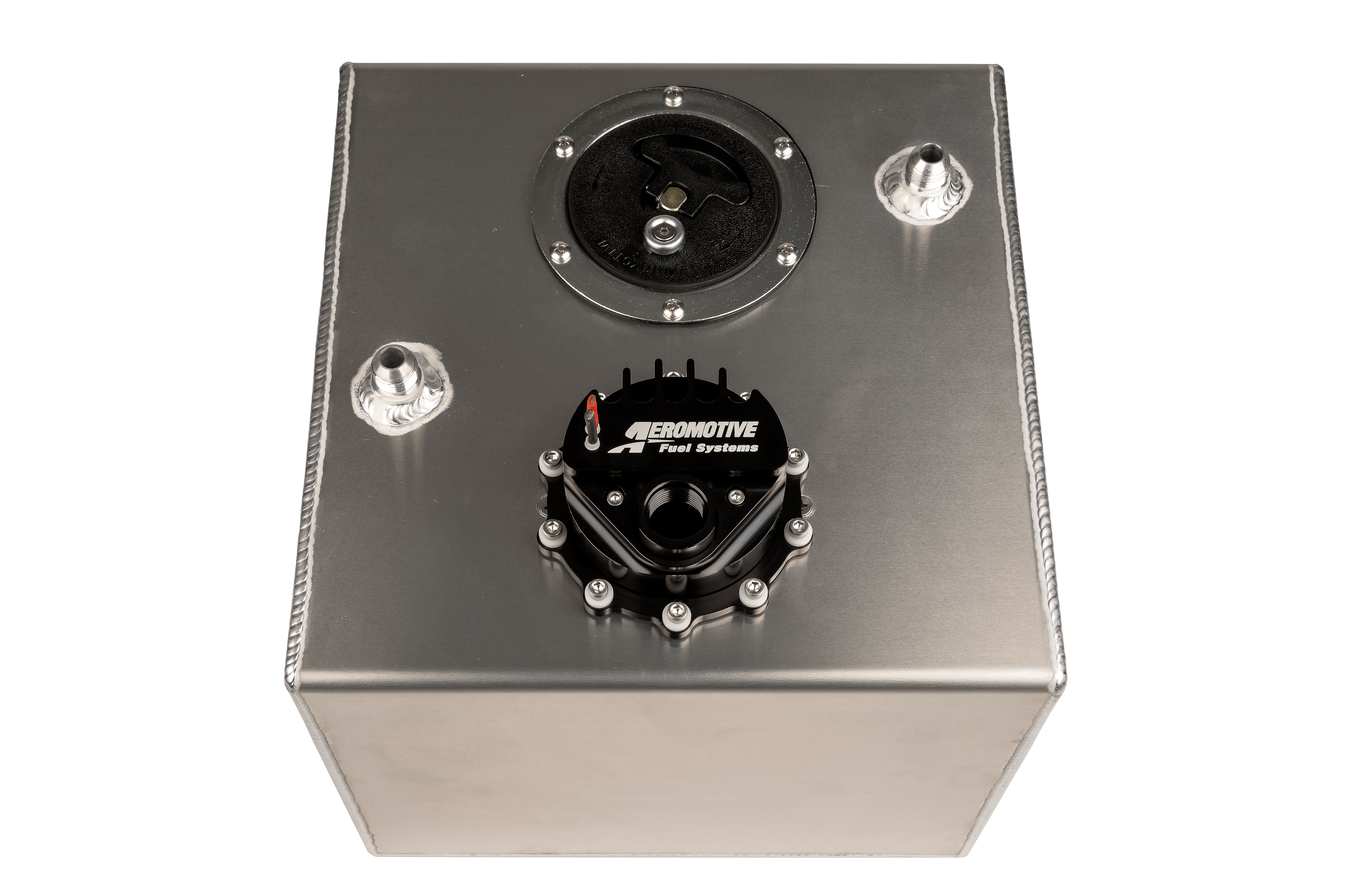
One solution for the Coyote would be an Aeromotive 15-gallon fuel cell plumbed with a 3.5 gpm in-tank pump. This would supply sufficient fuel but would be way over-capacity at part throttle. With a half-tank load of fuel, a 3.5 gpm pump would completely circulate the fuel load in 2 minutes! It would be much smarter to add a Phantom 340 pump to this cell to operate at low load, triggering the main pump once boost is achieved.
In the case of this centrifugally-supercharged Coyote engine, it started with a base fuel pressure of 58 psi to which power-mongering eventually added 24 psi of boost. This produced a total fuel pressure requirement of 82 psi (58 + 24). This puts a significant strain on the fuel pump.
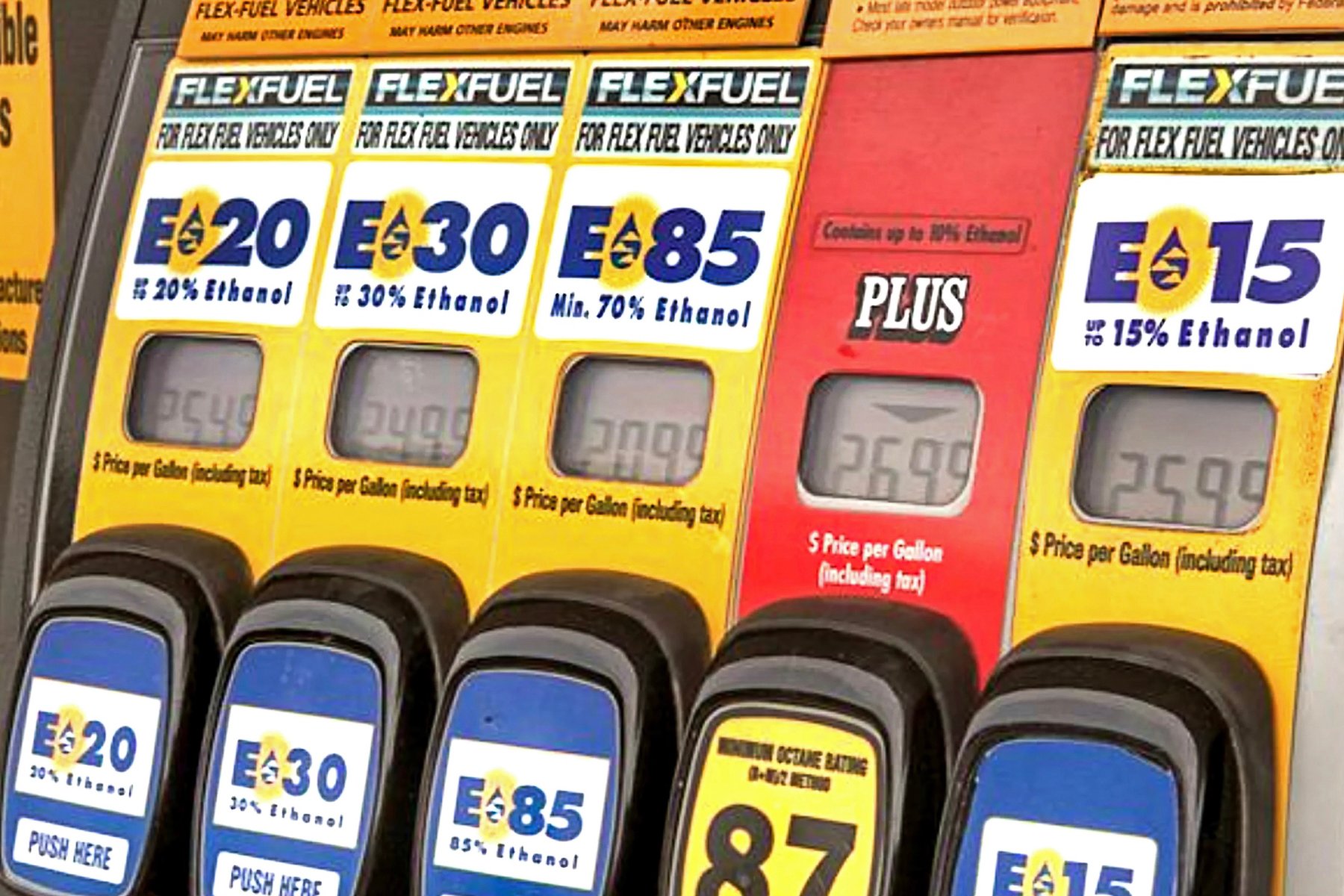
Adding to this burden is the volume of fuel demanded by using E85. This ethanol-based fuel has a lower BTU heat content than gasoline, which means in order to make the same power with E85, we must burn roughly 30-percent more fuel compared to gasoline.
Pressure drop over a long feed line is also a major concern, especially with E85’s high fuel flow requirements. At extreme horsepower levels it’s a balancing act between short length and diameter to maintain decent fuel velocity as well as flow.
Pump Selection
Now that we have a handle on the basic requirements, we can dive a little deeper into the details required to choose a pump that will do the job. Sure, we could find a pump with an advertised horsepower number in excess of our goal and be done with it, but let’s apply a little science to this selection process to gain an appreciation for the numbers. While a huge pump will do the job, let’s finesse this a little bit.
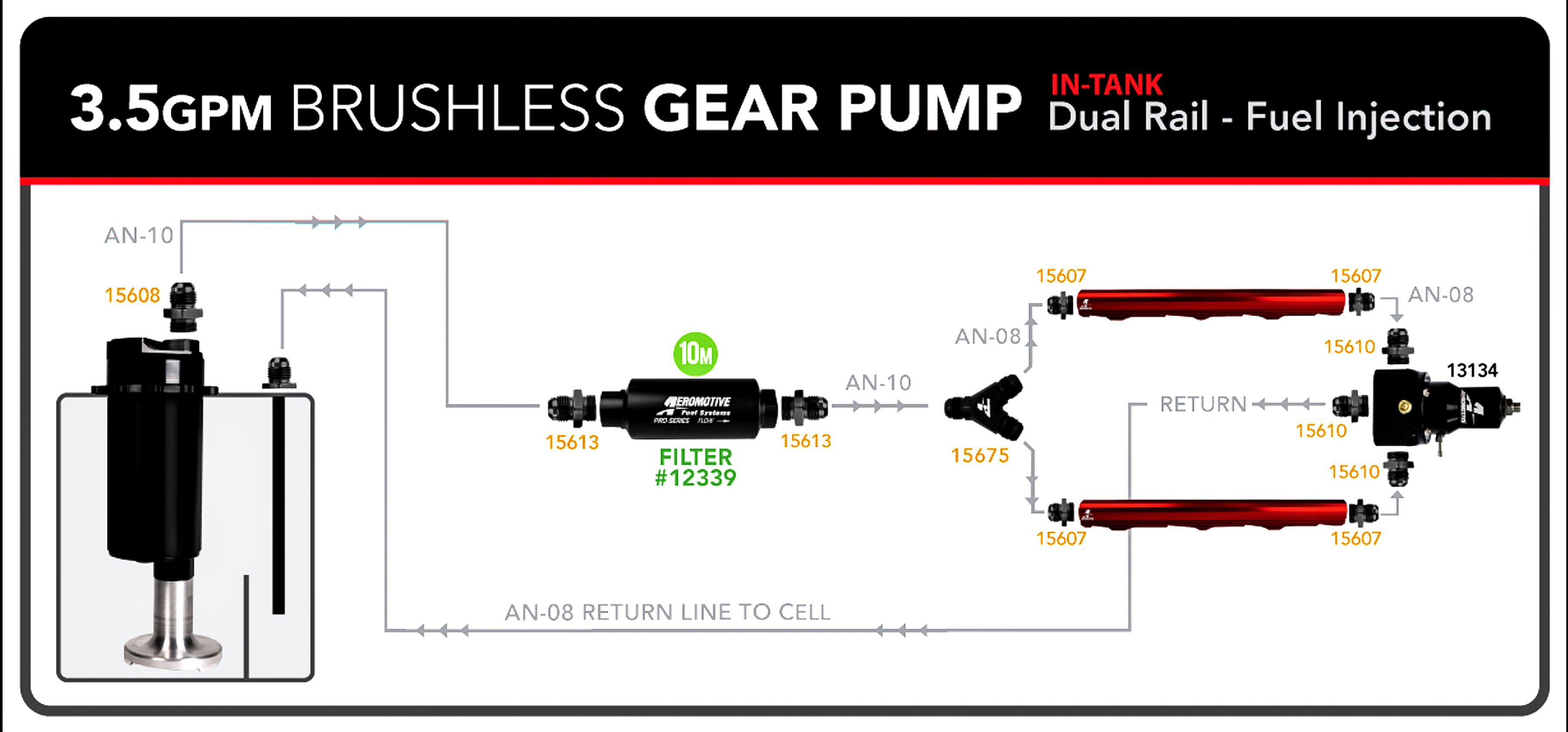
This Aeromotive schematic illustrates a typical high-demand system for a 3.5 gpm pump. This would easily flow sufficient fuel to feed upwards of 1,200 horsepower on a supercharged EFI system running E85 fuel. According to Aeromotive’s Technical Director Brett Clow, an intelligent selection process to determine a pump size for this EFI Coyote must start with consideration for injector sizing in order to select the right fuel pump.
The goal was 1,200 horsepower with E85 and a blower. Brett suggests looking up Aeromotive’s BSFC chart (shown below). In the chart, an E85 supercharged, EFI engine calls for a fuel delivery system efficiency rating of 0.90 BSFC. Remember, this number is intended to be at the high end of the range for a supercharged engine. The engine’s actual operating BSFC number could be a few hundredths of a point lower (more efficient) but Aeromotive wants to ensure that the pump will supply sufficient fuel. To estimate flow, simply multiply 1,200 horsepower x 0.9 BSFC = 1,080 pounds of projected fuel per hour. When we divide that by 8 injectors and add 15-percent for a duty cycle safety margin (85-percent maximum injector duty cycle) we come up with 155 lbs/hr. for each injector.
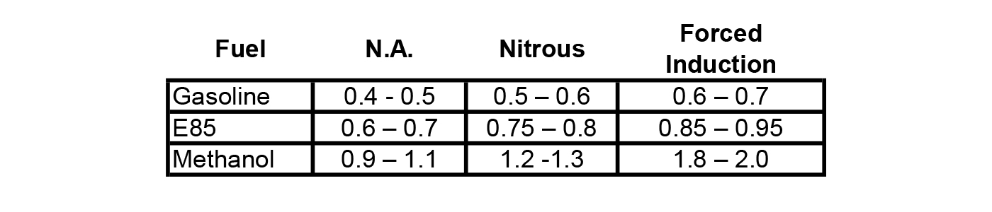
Brake specific fuel consumption (BSFC) is an expression of the maximum power amount of fuel, in pounds, consumed to produce 1 horsepower for one hour (lbs/hp/hr). This chart depicts Aeromotive’s BSFC numbers for various naturally aspirated (N.A.) and power-adder applications, and fuels used to determine fuel pump capacity. Note that E85 demands roughly 30-percent more fuel than gasoline while methanol doubles the volume of fuel compared to gasoline.
Ideally, we would prefer to have these injectors rated at a lower pressure like 43 psi. That’s better because this reduces the fuel pump’s pressure requirement because the manifold will be pressurized and we must boost-match the fuel pressure at a 1:1 ratio. With a boost pressure of 24 psi that puts a base of 43 + 24 = 67 psi. Most injectors today are still rated at 43 psi (3 bar) base pressure, but many are moving to flow ratings based on 58 psi (4 bar). Make certain you know the test pressure used to determine the injector’s flow rating. If the injector is rated at 58 psi, and you set the base pressure at 43 psi, it will flow less than its advertised flow rate.
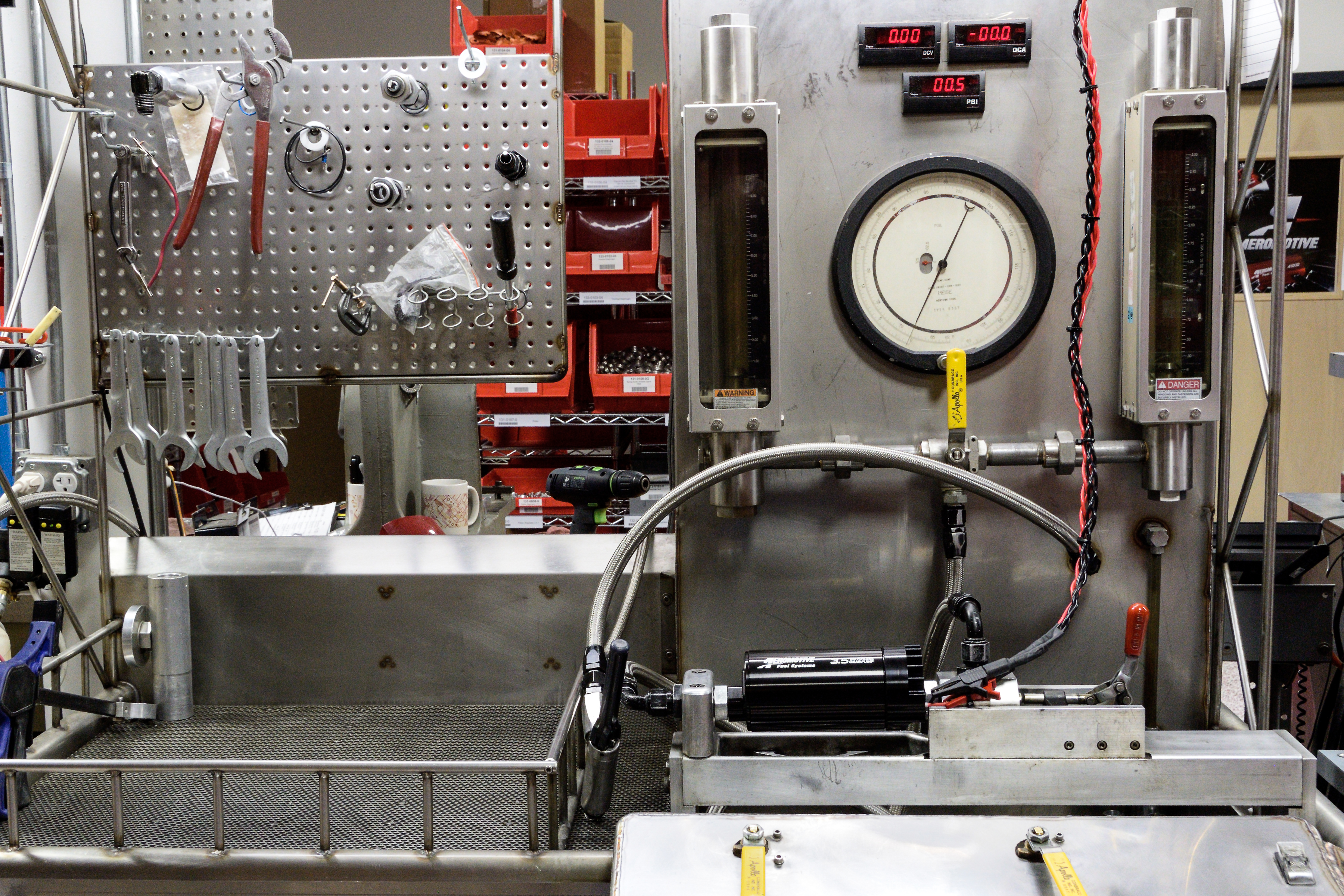
The only way to know for sure that a pump delivers is to test it. Aeromotive’s facility tests all its pumps for capacity and lists the pump output flow curves in the catalog so you know what you’re getting.
Our pump still has to move a huge amount of fuel at this higher line pressure. As mentioned earlier, pump output decreases as pressure increases. So with an injector that allows a base pressure of 43 psi and a boost pressure of 24 psi, our line pressure is now 67 psi. Looking at various pump output versus pressure curves, it becomes obvious that pump output decreases as pressure increases. Clow says all electric motor pumps slow down, and flow less, as pressure rises. Plus, all pumps—electric or mechanical—can lose efficiency at higher pressures because internal leakage will reduce efficiency. It’s critical to ensure you select a pump that moves enough fuel enough at the peak fuel pressure, base plus boost, the engine will require.
Conversion Table:
- Liters per hour to pounds per hour: LPH x 1.59 = Lbs/hr
- Example: 250 lph x 1.59 = 398 lbs/hr
- Gallons gasoline to pounds: Gal. x 6.2 = Pounds
- Example: 79 gal x 6.2 = 490 lbs.
- Gallons E85 to pounds: Gal. x 6.5 = Pounds
- Example: 15 gal x 6.5 = 97.5 lbs.
- Liters to gallons (gasoline): L x 0.264 = Gallons
- Example: 300L x 0.264 = 79.4 Gal.
- Cc/minute to lbs/hr: cc/min. / 10.5 = Lbs/hr
- Example: 1,200 cc/min./ 10.5 = 114.3
- Lbs/hr to cc/min: lbs/hr x 10.5 = cc/min
- Example: 85 x 10.5 = 892 cc/min
Aeromotive has recently introduced its new Pro Series of brushless electric pumps that can move an enormous amount of fuel even at high pressure. There are two versions rated at 3.5 and 5.0 gallons-per-minute (gpm). The 3.5 gpm pump will deliver 3.5 gpm x 6.2 (pounds per gallon) x 60 (min. per hour) to equal 1,302 lbs/hr of fuel flow. Aeromotive also offers its Eliminator brushless pump rated at 3.0 gpm delivering 1,116 lbs/hr of fuel at 70 psi, but that’s just barely enough for this particular application, since our earlier math indicates the Coyote needs 1,080 lbs/hr We really need a pump capable of 1,250 lbs/hr at the same 70 psi, so it looks like the 3.5 gpm Professional Brushless Gear pump is the way to go in this instance.
How Line Size And Electricity Affects Pump Performance
But we’re not done yet. Another essential consideration is the potential pressure and flow loss related to fuel line size. Aeromotive shared some in-house flow data to drive this home. Assuming this supercharged Coyote will be used on the street with a fuel cell in the rear of a long wheelbase car, it’s not unusual to see a 15-foot length of fuel line between the fuel cell and the engine.
We’ve created three abbreviated charts pulled from Aeromotive’s data. These pressure drop charts are based on rubber-lined AN fuel hose. If you were to use hard line or smooth PTFE line, the pressure drops would likely be slightly lower. Note the major effect hose length has on pressure drop. While hose diameter is critical for volume, it’s obvious that length adds to the load that the fuel pump must support.
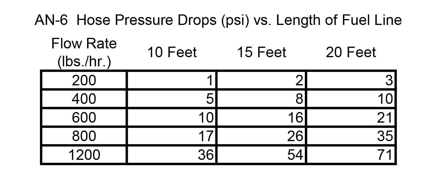
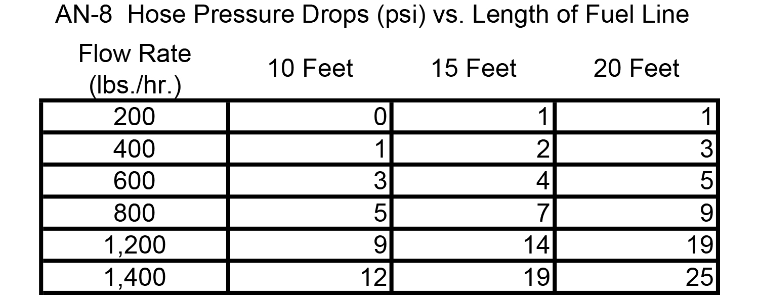
A quick way to equate lbs/hr to horsepower is to divide flow by the bsfc. Example: 600 lbs/hr / 0.50 bsfc = 1,200 hp. This example uses a normally aspirated, gasoline bsfc. As you can see by the charts, it would not be wise to plumb a 1,200 lbs/hr system with -8 line through 15 feet since that would generate a fuel system pressure drop of 14 psi.
Clow also pointed out that making the fuel line too large as an over-compensation for pressure drop can also cause problems. He mentioned that some big race teams have discovered that oversized fuel lines/fuel rails can kill flow velocity, which should be 3 to 12 feet per second on the pressure side of the system. An overly large fuel line will develop excessive fuel pressure fluctuations. Big may be good, but bigger is not always better!
One further check to ensure the fuel system operates at maximum efficiency is to pay close attention to the electrical side of the pump. As you can imagine, amperage demand also increases with higher fuel pressures. This places an increased load on not only the charging system to supply the necessary current and voltage; it also requires reviewing wire gauge to ensure it can handle the current and prevent voltage drop to the pump.
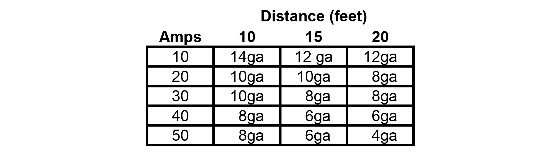
The above chart lists the wire gauge size recommendations depending upon the combination of the pump’s current draw and the length of the wire running from the power source to the pump. This chart assumes no more than a 3-percent voltage drop. Always use the same gauge wire for the ground circuit.
We’ve included a chart listing Aeromotive’s brushless pumps all pushing against a 60-psi head pressure. The smallest of the pumps requires just over 11 amps while the big pump spikes the load to 24 amps. At full song it might be necessary to employ a charging system capable of 100 to 140 amps to handle ignition, fans, accessories, and the fuel pump to ensure the voltage remains stable.
Once the charging system is spec’d, even a small pump demanding 20 amps over a 15-foot length of wire will benefit from an 8-gauge wire to minimize the voltage drop. The best way to ensure the entire system is sized properly is to perform a dynamic voltage drop test. This could be done with a volt meter, or better a data recorder monitoring the voltage at the fuel pump under max load. If the voltage drops below 13.5 volts yet it shows 14.3 volts any other time, you then know you have a 0.80-volt loss and there is work to be done to bring that drop closer to 0.40-volt or less.

In Conclusion
Maintaining voltage at the pump is critical since voltage is torque to an electric motor and torque is what keeps the pump from slowing down as pressure rises. Aeromotive pump flow curves plot both 13.2 volt (battery only) and 14.4 volt (alternator-equipped) applications. It’s obvious looking at the flow curves that keeping voltage at 13.5 volts or better is important to maintain expected fuel flow volume. Of course, higher voltages (14.5-16.0 volts) will make the pump run stronger. This is the idea behind voltage-boosting boxes that bump the system voltage to the fuel pump. While this does increase pump output, it comes at the price of reduced pump lifespan.
While it may appear that choosing a fuel pump is a complex process, hopefully we’ve illustrated that it’s not black magic and that with careful planning you can design an efficient fuel system for virtually any engine. Making power means paying attention to the details. When that happens, your efforts make success look almost effortless.