
Preparing an engine to achieve maximum performance requires careful consideration in parts selection, machining and assembly. There are dozens of components that must work in harmony to produce the efficient cylinder filling, and combustion, which will ultimately deliver maximum thrust on the pistons. When horsepower increases are discussed, the first thought is often the induction system, but in order to reap the maximum benefits of ported head and intake combinations, or forced induction, the valvetrain must be up to the task.
Whenever moving to a bigger cam and/or higher RPM, special consideration must be given to the lifters, pushrods, rockers, valve springs, retainers, and keepers. If the valvetrain is not operating in a controlled manner (meaning you have valve float or bounce), performance will suffer. Additionally, poor parts selection or improper setup can rob power and/or lead to a costly and catastrophic failure. It’s hard to be consistent or win races when your engine encounters valve float, dropped valves, or valve-to-piston contact. The key, then, is to select the best parts for your application.

This is a typical hydraulic flat-tappet lifter. It uses oil to cushion the pushrod and valvetrain. Hydraulic lifters use zero valve lash so they are low maintenance and operation is quiet.
To get a better look at today’s lifter technology, we turned to the experts at Comp Cams and Jesel Valvetrain.
“We really do not design ‘camshaft profiles,’” says Comp’s Trent Goodwin. “Maybe that was the way things were done in the 1970s and ’80s, but from the late 1990s through today we always start by designing valve motion. After you develop the lift, velocity, acceleration, and jerk curves you want for an application, then you work backwards though the rocker arm, to the pushrod, and back to the required tappet motion to produce that valve motion. Knowing the required tappet motion, the cam profile is calculated using the theory of envelopes to determine the requisite cam surface.”
Goodwin continues, “From looking at valve motion design, the role of the lifter becomes clear. You are calculating a lifter position at every cam degree that is required to convert the linear position of the valve from its rest on the seat to the angular position of the camshaft as it is driven at half crank speed.
“In mathematics and physics, this relationship is known as a coordinate transformation and often solved with Laplace Transforms. If you ever need sleep, look up the mathematics of exactly how they work. Please remember we are far more concerned with valve motion than anything on the cam and lifter side. Those components are developed under some geometric constraints to produce the desired motion of the valve, and never the other way around.”
“Fortunately, the industry has worked hard to improve valvetrain performance,” adds Jesel’s Rob Remesi. “Spintron machines and computer-aided programming, combined with improved materials and manufacturing have given us the tools to build engines with more camshaft lift, greater ramp rates, and at the same time allowed engines to maintain valvetrain stability, even when engine speed exceeds 10,000 rpm.”
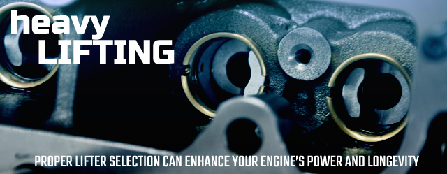
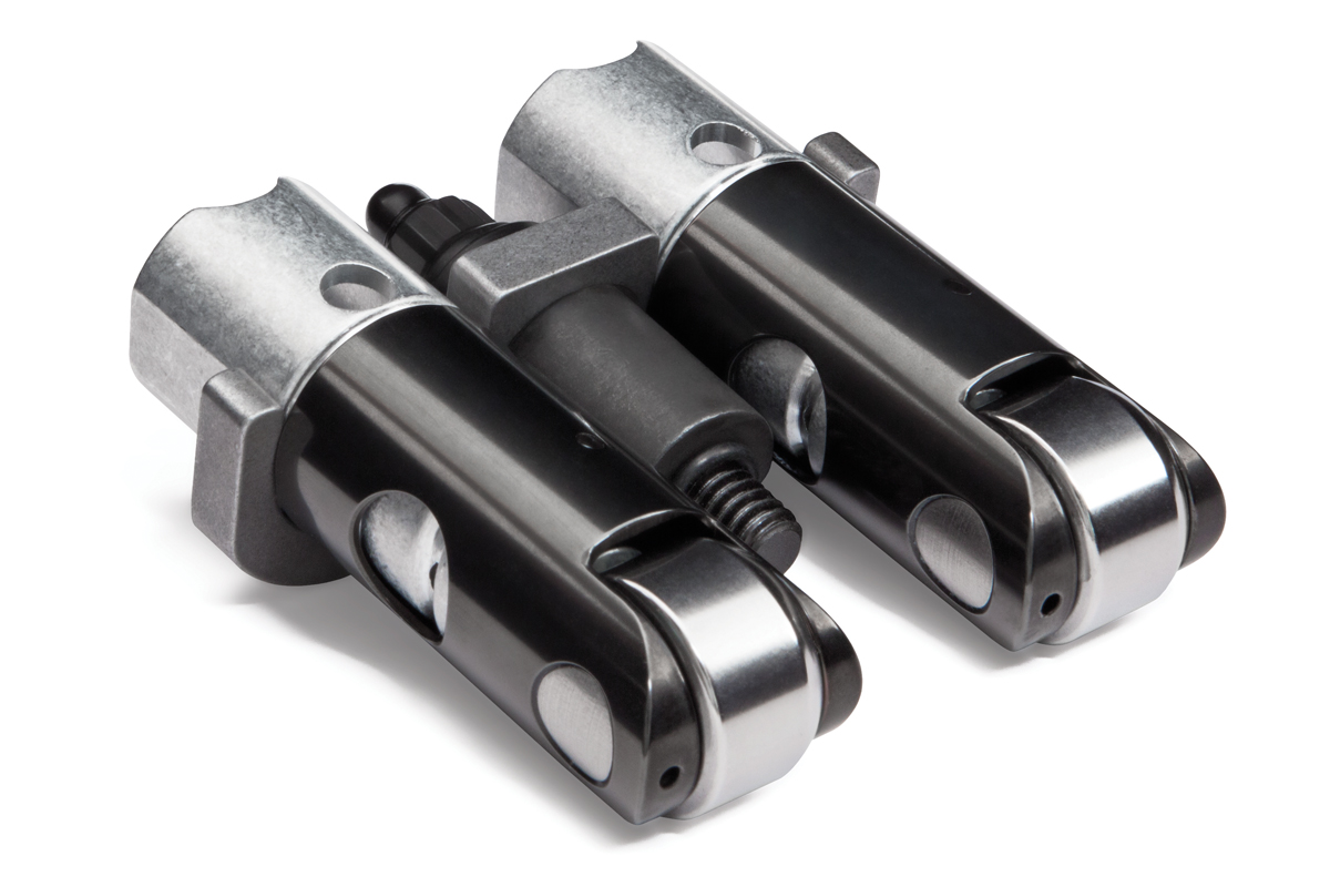
Solid lifters, like these tie-bar units from Jesel, utilize a roller wheel that allows for extremely aggressive camshafts without fear of deflection or lost performance.
Bits And Pieces
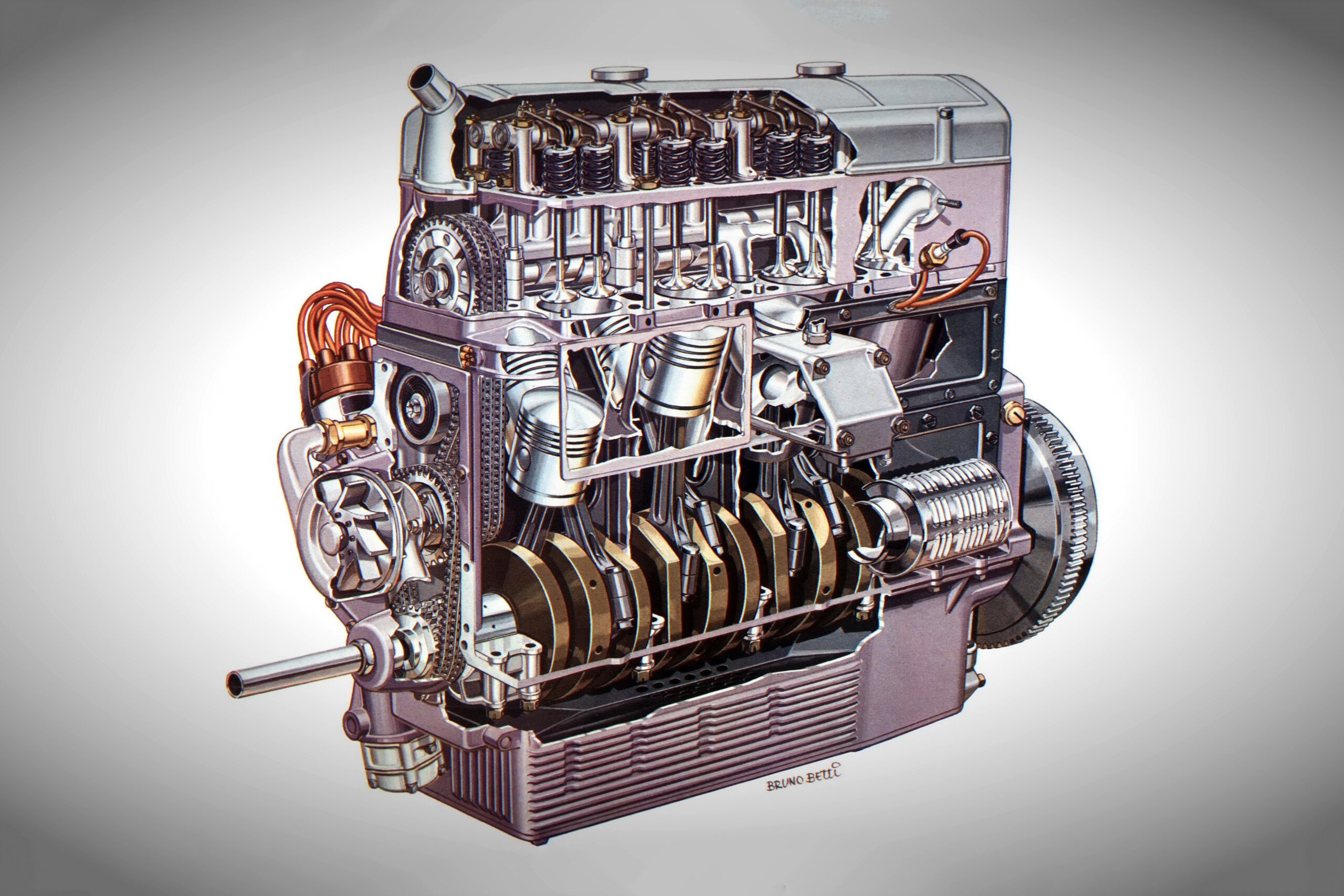
A typical cam-in-block engine uses lifters, pushrods, rocker arms, valve springs, valve spring retainers and retainer locks. The purpose of the valvetrain is to convert the spinning motion of the camshaft to the up and down action of the valves.
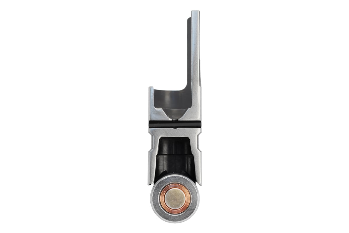
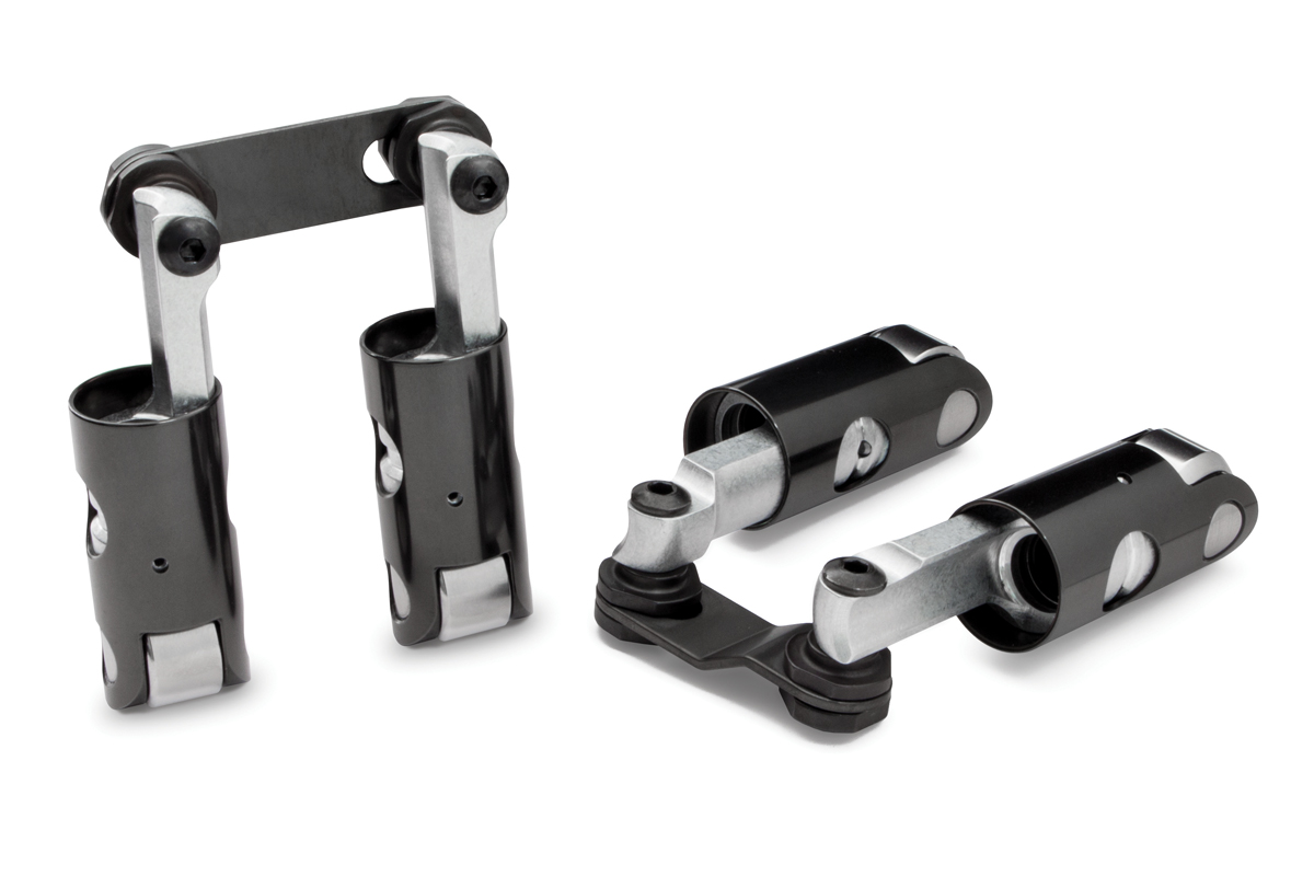
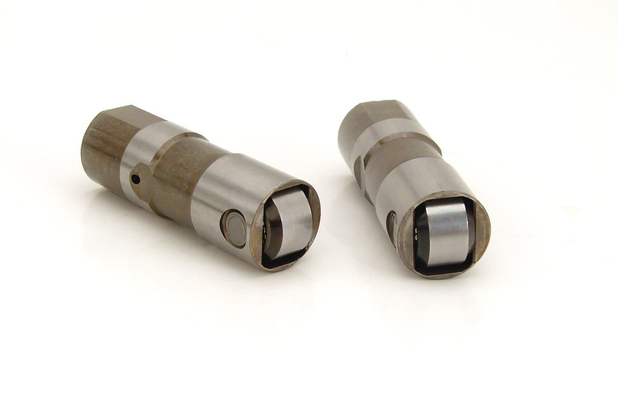
These cut-away shots show the simplicity of the solid lifter (left) and its lack of internal moving parts as compared to a hydraulic piece with its internal spring and plunger(right).
It is the desire of any engine builder to have the valves open and close when directed to — but that doesn’t always happen. Aggressive cams can loft the lifters (and the valves) past the desired lift point, meanwhile deflection in the pushrod can prevent maximum lift from being achieved, and weak springs can cause float or bounce. Just because the valvetrain components are designed for severe duty doesn’t ensure they’ll work as designed. Keeping the valvetrain operating properly is not an easy task, and often, things that would normally make a valvetrain run smoother can actually have the opposite effect.
Once the cam is spinning, the dance of the valvetrain leads off with the lifters. Lifters ride directly on the cam lobes and transfer the lifting motion to the push rods. Actual valve lift and duration are dictated by the shape of the lobe and the rocker ratio. The pushrod, when acted upon by the lifter, lifts one side of the rocker arm, and much like a see-saw, the opposite side of the rocker is forced down to manipulate the valve. The valve spring provides resistance and allows the valve to shut on the closing side of the lobe.
In order to feed the engine maximum airflow, it’s common to increase not only the lift and duration, but also the speed at which the valves open and close. Steeper ramps on the lobe snap the valvetrain into action. This increases the load on the valvetrain and it often requires increase spring pressure. Of course the effect of this causes additional loading on the pushrod, lifter, and camshaft, too. To prevent failures, the aftermarket has developed more robust lifters that utilize stronger materials, and ones that are larger in scale as compared to factory components.
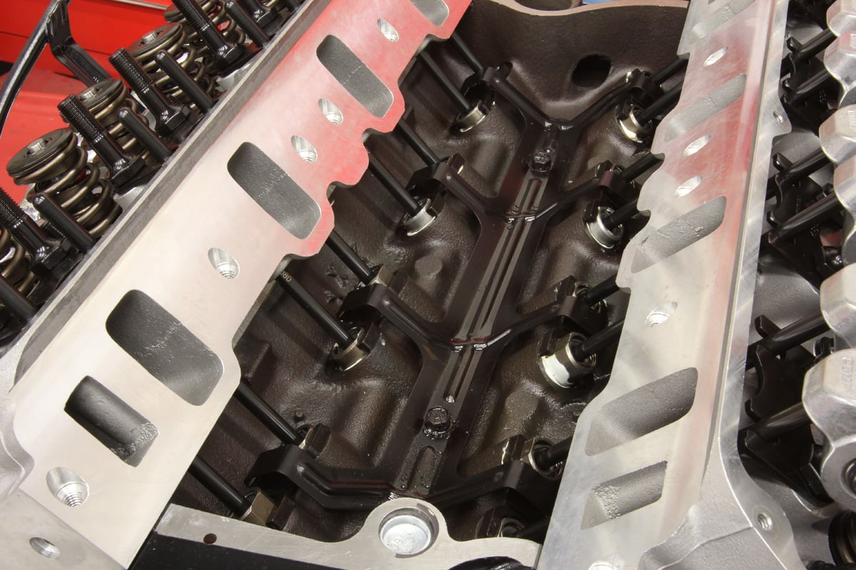
Here’s a set of performance hydraulic roller lifters installed in a late-model small-block Ford. Note the tie-down bar that retains the lifters.
Lifter Types
Lifters are cylindrical in shape and fit into a lifter bore within the lifter valley in the engine block. Cam-in-block V8 engines use one cam and each bank of lifters sits at a 90-degree angle to the opposite side of the engine. A two-valve-per-cylinder engine will have two lifters per cylinder, one for the intake valve and one for the exhaust valve.
There are four basic types of lifters/tappets:
- Hydraulic flat
- Solid flat (mechanical flat)
- Hydraulic roller
- Solid roller (mechanical roller)
“The primary differences in these are clear from the name,” says Goodwin. “However, the hydraulics use internal hydraulic automatic lash adjustment, where the solid or mechanical systems require another means for the engine builder to set the lash. The flat or roller refers to the lifter interface with the camshaft. The flats are sometimes referred to as sliding interface, where the rollers are designed with either a needle or bushing bearing system and a roller wheel to allow the interface to roll against the cam face.”
The motion of the valvetrain is controlled by the camshaft, but without a properly-designed lifter for the application, the pushrod, rocker arm, spring, and valve will not operate within their intended range, potentially causing performance loss, and worse, damaged components.
Jesel builds lifters by application and price point. “All our lifters are built on the same CNC machines with the same precise tolerances and the same manufacturing processes that have given Jesel its reputation of being the most reliable and hence the best value in roller lifters out there,” says Remesi.
“You only have to trash one $80,000 engine due to a lifter failure to figure out where the value really is. What makes a Jesel lifter? Tool steel bodies and rollers, internal oil circuits, machined tolerances to .0002-inch, larger-diameter axles then industry standards, REM finishing with DLC coatings, stainless steel tie bars and the fact that they are rebuildable are just a few of the ingredients.”
Remesi continues, “Dan Jesel often quips that it took him 20 years to get to this point. Its manufacturing capability (.0002-inch) tolerances are unheard of for the automotive sector, and the specialized heat treats and materials. Jesel has a full lab that tests the raw materials as they come into the factory to make sure they the correct alloys.”
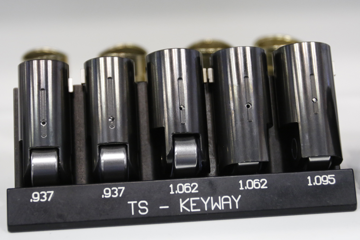
Jesel also sells a complete line of lifters (and other valvetrain components) to suit many performance levels. Here is how they all fit together in the Jesel lifter hierarchy. “The Jesel tool steel keyway lifter is the no-holds-barred ultimate Pro Stock, Pro Mod, NASCAR type of lifter,” stated Remesi. “It uses the best materials and coatings possible and its light weight (as little as 95 grams) is extremely easy on an extreme RPM valvetrain. A low pushrod cup location reduces side thrust and offset pushrod cups and patented offset rollers enable straight/stiff pushrod paths even with today’s large ports.
This is the Jesel dogbone lifter. Dogbone lifters derive their name from the dogbone-shaped steel retainer that bolts to the block and maintains lifter alignment. They are lighter than tie-bar style lifters and are an alternative to keyway lifters because they do not require special lifter bushings to be installed in the block. The Jesel dogbone retainers can be easily installed with a simple drill jig available from Jesel. Standard features include an ultra-light design, pressurized roller oil circuits, hard-coated steel bodies, aluminum pistons, hardened-steel pushrod seats and internal axle locking pins.
Next in the Jesel food chain is a tie-bar version of the tool steel (TS) lifter for those who don’t want to be bothered with bushing the lifter bores, but want all of the high-end features the TS brings to the table. The dog-bone style lifters are an offshoot of current OEM engine design hydraulic lifter guide system. It provides a bridge between the super lightweight keyway style lifter and the heavier traditional tie-bar style by eliminating the weight of the tie-bar and its towers. However, the extended bodies that are guided by the steel dog-bone retainer plates sometimes interfere with the pushrods and are best used in applications without severe pushrod angles.
You only have to trash one $80,000 engine due to a lifter failure to figure out where the value really is. — Rob Remesi, Jesel Valvetrain Innovation

“In the real specialty market, Jesel’s Nitro/Alcohol lifters have introduced a new level of brute strength and durability to a class of engines that literally crush roller lifters. Jesel’s latest innovation (the cartridge lifter) is a modular “wheel-guided” lifter and sleeve that slips into the lifter galley and is retained by a single bolt or stud and in the event of a rare failure, the single lifter and bushing assembly can be removed and replaced in minutes. The cartridge lifter requires an aftermarket block that has enough room to accommodate the oversized bushing,” says Remesi.
The Jesel keyway lifter. Most notable is the lack of a link (tie-bar) connecting the intake and exhaust lifter pair to keep them aligned with the camshaft lobes. Instead Jesel bushed the lifter bore with a special bronze alloy bushing with a keyway groove cut for a special hardened pin on the lifter body. The pin rides up and down in the keyway groove, keeping the lifter aligned with the cam. This removes considerable weight from the lifter; the weight of the tie-bar is eliminated and the lifter body is much shorter as a result.
Solid/Solid Roller
As the name implies, a solid lifter is one solid cylindrical unit with a “nearly” flat surface on the bottom, which rides on the cam lobe and a cup on the opposite side to capture the push rod. Solid lifters require valve lash to compensate for thermal expansion of the parts. This adjustment is normally made using a feeler gauge between the rocker and the valve tip. While solid lifters have the potential to produce more power than hydraulic lifters, they can be noisy and they do require regular adjustment.
Basic solid flat-tappets are inexpensive, but there are drawbacks. Most flat-tappet cams require a specialized break-in routine, and you’ll be limited on lobe design due to interface between the flat bottom of the lifter and the angle of the cam lobe. As the lobe gets more aggressive, so does the angle between the edge of the lifters and the lobe itself.

Comp’s Elite Series race lifter offers an 8620 steel alloy body and .820-inch 9310 steel alloy wheel that’s been micropolished and features steel bearing needles. These lifters feature removable cups that allow the builder to determine the lifter offset and simply replace the cup with one of the appropriate dimension. These require bronze bushings to be fitted in the block.
The answer is a solid roller lifter, which incorporates a roller wheel at the bottom. The roller rides directly on the camshaft, reducing friction and allowing much more aggressive lobe profiles. Most of today’s factory performance V8 engines come with hydraulic roller lifters, as they provide the performance of a roller cam, allowing quicker opening and closing rates, with the low maintenance and quiet operation of a hydraulic setup.
Lobe lift, and the motion of the lifter, push rod and rocker, continue to lift the valves off the seats (while compressing the valve springs) until max lobe lift is reached. Then the lifter follows the lobe on the downward side of the lobe. The spring forces the valve shut and keeps tension on the valvetrain. As one might imagine, as horsepower and rpm is increased, so is the load on these parts.
Hydraulic/Hydraulic Roller
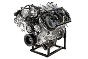
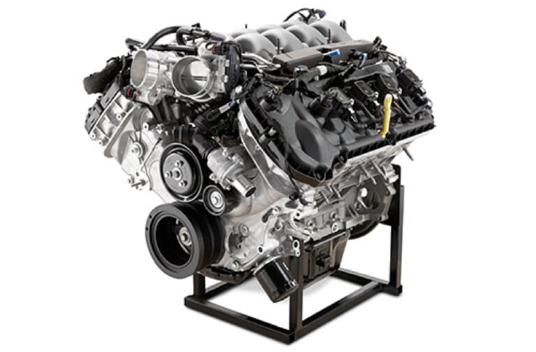
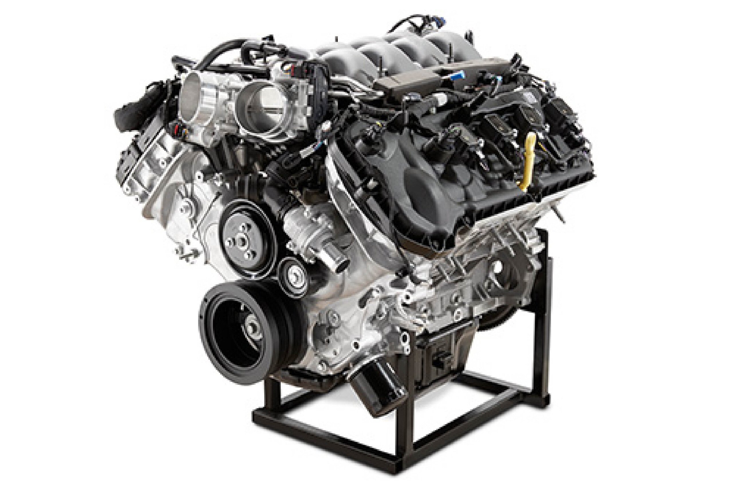
The hydraulic roller lifter has been used in many OE applications such as the original 5.0-liter Ford and all LS engines. They’ve proven their durability and effectiveness in these applications; when used properly in racing applications, they can be just as durable and efficient.
While solid lifters offer simplicity, great performance, and a reputation for being more “racy,” today’s hydraulic lifters can offer amazing performance, with less maintenance. Hydraulic lifters have been used by OE manufacturers for decades, even in many factory high-performance applications.
Hydraulic lifters take up the slack or lash in the valvetrain and can compensate for thermal expansion of the parts whether the engine is cold or at operating temperature. These lifters are complex, and use a cushion of oil to take the slack out of the valvetrain, eliminating the need for constant adjustment, and they can absorb harmonics in the valvetrain, which makes for quiet operation.
Hydraulic lifters are made up from a hollow steel cylinder with an internal piston that’s retained by a strong clip. Pressurized oil is fed to the lifter through an orifice in the lifter body. When the lifter is on the base circle of the cam, the lifter is free to fill with oil. But as the lifter is acted on and starts to lift, the internal piston blocks the hole preventing any more oil to enter the lifter. The trapped oil acts as hydraulic fluid and maintains the pre-load on the valvetrain as it travels over the lobe and through the cycle.

Is there a performance advantage between hydraulic and solid lifters?
“There is a performance advantage to each system,” says Goodwin. “The advantage of the hydraulic is especially evident in aluminum block and head applications. From cold to hot, the valve lash of these engines can change by well over 0.010-inch. Modern tight-lash profiles have very high acceleration immediately as the valve starts to move. If you miss the lash by as little as 0.004-inch from design, poor dynamics and component failure can result. With a hydraulic system, the lash is reset on every rotation. Hence, as the block and head temperature rises and the rocker arm moves farther away from the camshaft, the lifter automatically adjusts clearance for optimum lash.
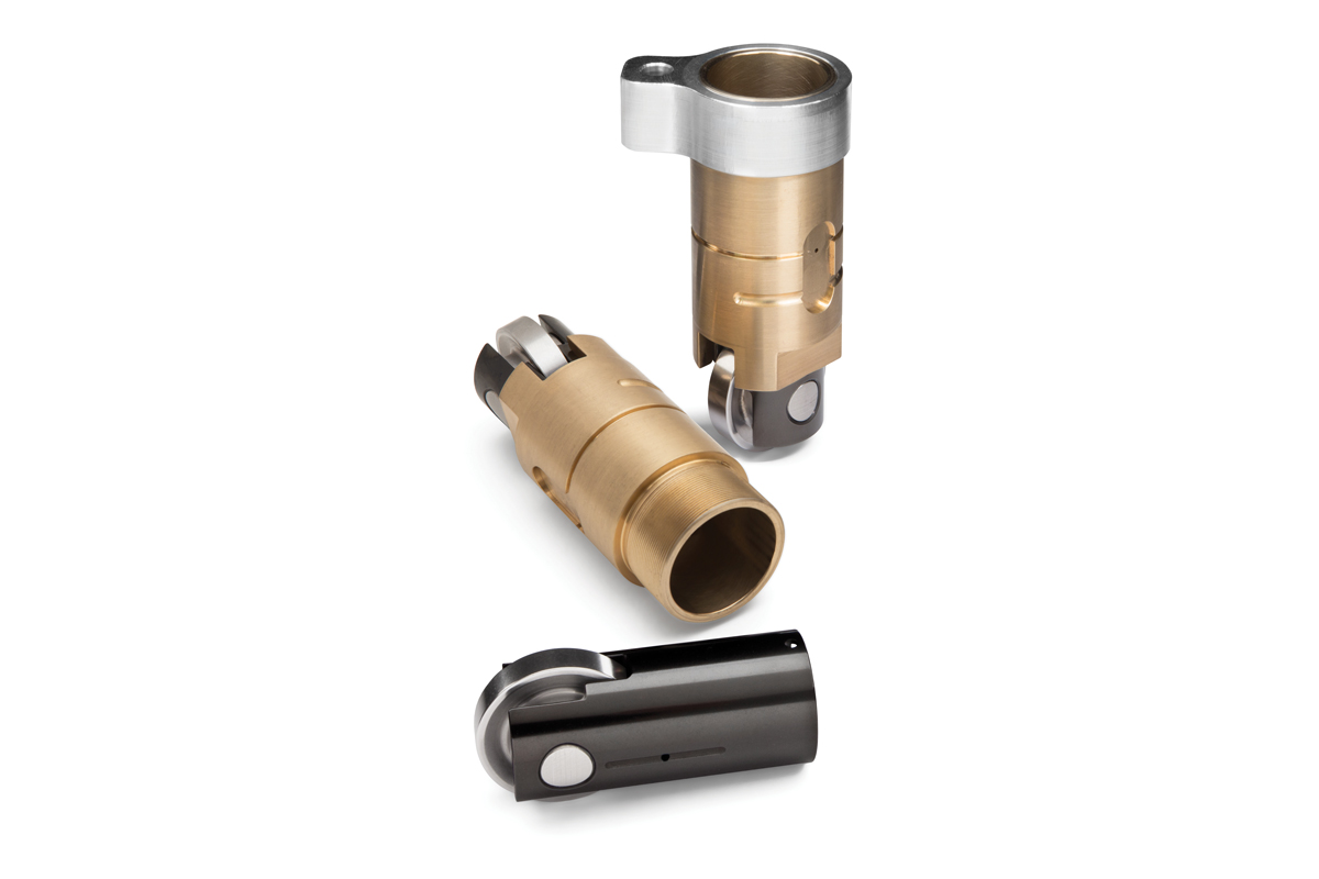
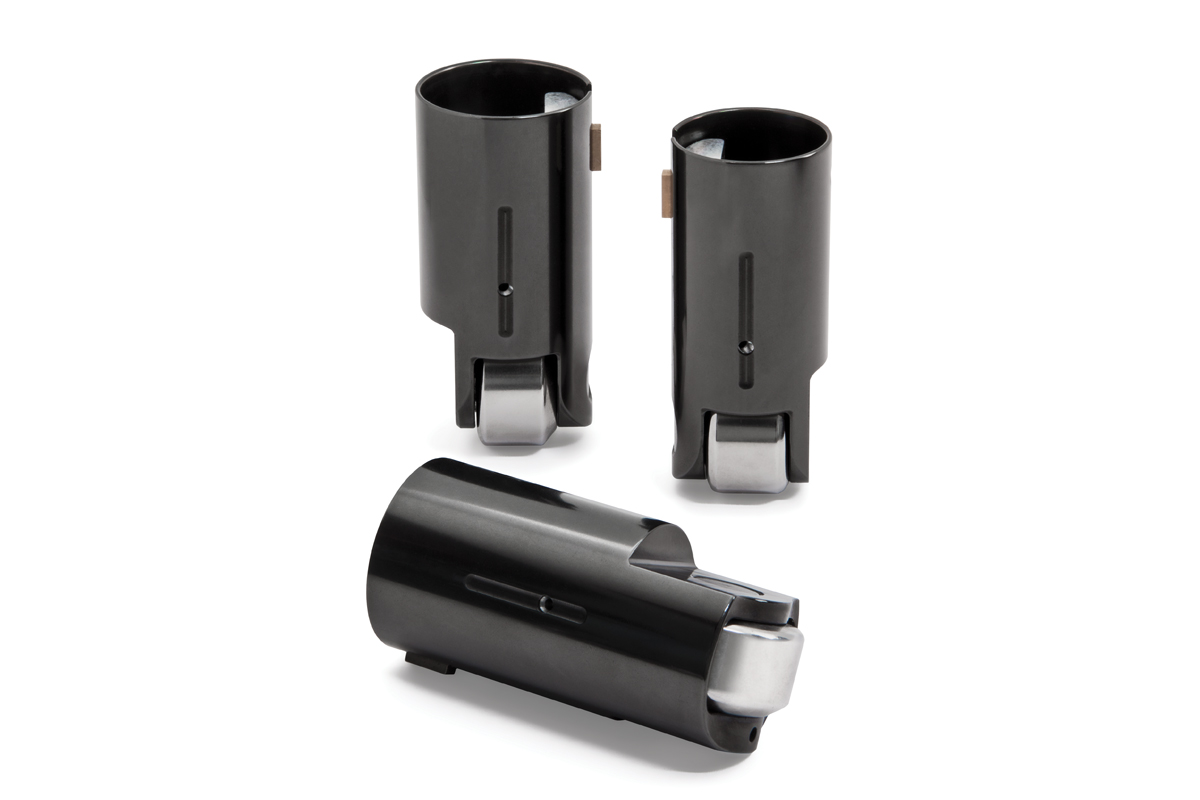
The Jesel cartridge roller lifter. This is a stand-alone roller lifter pair that contains the lifters and bronze bushings and can be installed or removed in an aftermarket block with a single retaining bolt or stud.
“The negative of the hydraulic is that under very high loads the trapped gasses in the oil compress and you gain clearance with load. As load increases with RPM, the effective lash and valve duration will decrease with RPM. Every year the hydraulic designs improve. Ten years ago we thought that 6,500 rpm was pushing the limit for good hydraulic lifter operation. Today, we have many hydraulic systems that will run closer to 8,000 rpm with excellent control.”
Material World
As with many race components, better and stronger materials are typically used in quality aftermarket lifters.
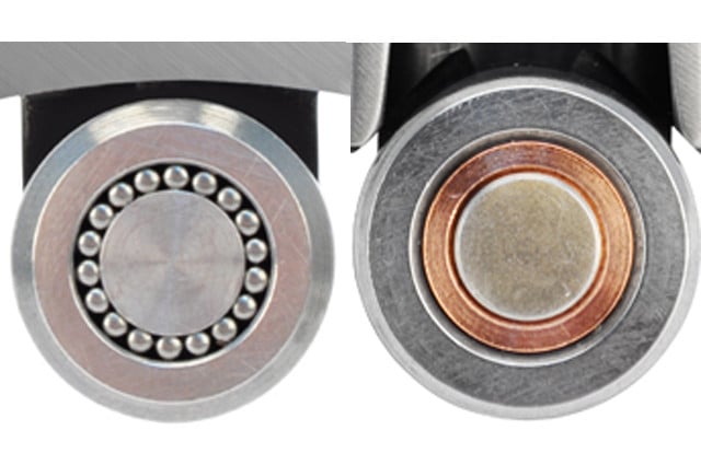
Bushings Vs. Needle Bearings
Jesel feels like roller bearing lifters have advantages over bushed lifters. It’s hotly debated. “The myth that needs to be debunked is that bushed roller lifters are superior to needle bearing lifters,” said Jesel’s Remesi. “Jesel has spent a lot of time and money in the development of the needles, roller, and the axle. If we felt the bushing roller was better we would have pursued it, but in most applications, where the loads and speeds are extremely high, the Jesel stance is the needle-bearing roller is a must. Unlike a rod or main bearing, there is not enough oil pressure available to a lifter roller to sustain an oil film needed between an axle and bushing to keep it from galling or wearing.”
Goodwin also chimed in on the same topic, but with a different take: “One myth we often hear is that ‘bushings are always better than needle bearings.’ Both needle bearings and bushings have their role and their individual strengths and weaknesses. Bushings are always higher friction and wear the cam significantly more, especially on the opening side, as the wheel may slow as it skids on the base circle with lash then have to speed up as it “lands” on the opening ramp. The total engine horsepower loss is not notable (well less than 5 hp), but it is real and does add heat to the oil and wear to the camshaft. That said, in turbo applications with boost controller systems that use an ignition cut, the exhaust valves can actually be lifted off the seat, resulting in dramatic lash and extremely high lifter-wheel impacts. In these applications, a bushing lifter performs much better than needles as the bushing spreads the shock over a huge surface compared to a needle. The bushing can also absorb more of the energy through material compliance.”
When asked to comment on materials, Remesi didn’t get into specifics. “The materials we use are proprietary custom blended exotic tool steels, which take specialized heat treat specs developed by Jesel,” he says.
There are many variations and price points of these products. This allows enthusiasts to select a lifter that suits the needs of their engine.
“For our Sportsman solid roller lifter design, we took everything we learned for our Elite Series lifter, incorporating the exact same link bar guide system and body material. But we made a new body more like our lower-priced Endure-X Series except with a much shallower oil groove and taller walls,” says Goodwin.
“This increases stiffness and reduces lifter bore wear, permits improved oiling to the bearing. We also use deep-pocket milling under the wheel to reduce mass. We introduced this lifter with the choice of needle bearing, which offers minimal friction and maximum endurance in controlled systems, or bushing bearing, which best withstands high loading in systems of marginal high-speed control or those combinations that see significant use of turbo stutter boxes or are often run against a hard rev limiter.”
The company also offers their new Short Travel XD hydraulic roller lifter, which is designed to minimize the oil volume and air bubbles in the high-pressure side of the lifter.
“Engine oil can be closely approximated as an incompressible hydraulic fluid under laboratory conditions. However, in running engine conditions, oil aeration always occurs. On the high-pressure side of any self-adjusting hydraulic lifter system, the tiny air bubbles suspended in the oil can, and will, compress, resulting in effectively looser lash at high engine speed,” says Goodwin.

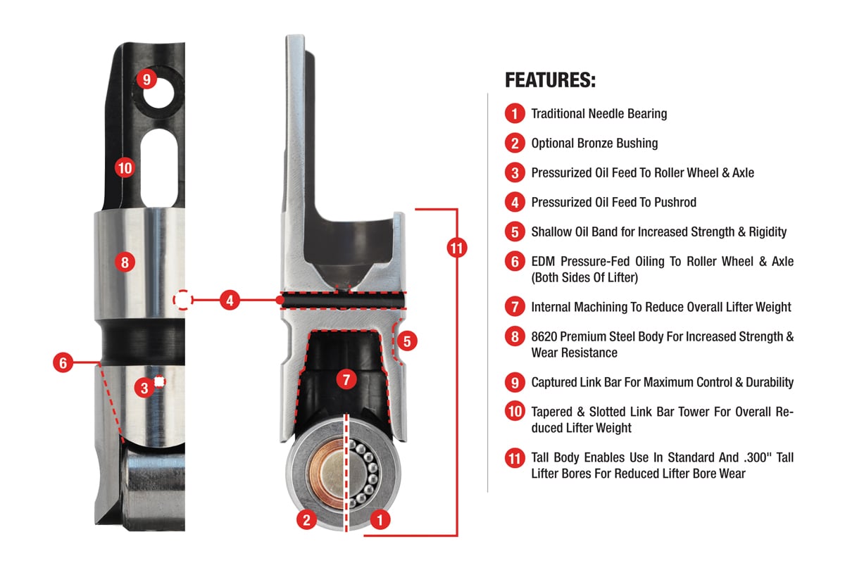
Comp Cams' Sportsman lifters are offered in two configurations; a traditional needle-bearing wheel design or the company's optional bronze bushing axle/wheel setup. Regardless of design, there are two pressurized oil feeds to the axle, along with an edge orifice to feed oil to the lifter wheel. The oil band size has been reduced in depth to enhance rigidity, and the lifters are internally machined to help reduce weight. The rebuildable design has staked axles to reduce failure points, while the skirted wheel is designed to strengthen the lifter's ears.
Adding more options to that product line, Comp is introducing Short Travel XD hydraulic roller lifters this year with an upgraded tool steel pushrod seat to withstand the harsh demands of even the most severe applications, including 24-hour endurance road racing and offshore marine competition applications.
Another piece of the lifter science that can’t be overlooked is the increase in lifter diameter. Larger lifter body diameters are required to accommodate larger roller diameters. A larger roller slows the speed of the roller and needles down and will increase the wall thickness between ID and OD, and will also reduce the pressure angle that the lifter will see.
“On flat tappet systems — both hydraulic and solid — the maximum allowable tappet velocity corresponds directly to the maximum tappet diameter,” says Goodwin. “For example, a 0.842-inch tappet will run off the edge when the velocity goes past 0.007-inch tappet lift per degree, perhaps a bit more depending on face chamfer and lifter bore alignment. For a 0.875-inch tappet you can get about 5 percent higher maximum tappet velocity, and a 0.900-inch lifter will allow about 8 percent more velocity higher than a 0.842-inch tappet. If you think about a speed limit on an expressway, that is somewhat how maximum velocity works in cam design. If the maximum velocity can be higher, then we can both achieve higher lift and/or more area under the curve.”
By making the roller lifters larger in diameter, it allows Jesel to offer them with centered and offset pushrod cups to reduce pushrod angularity. The larger body lifters are available with .050-inch or .150-inch offset pushrod cups. Another one of Dan Jesel’s tricks is to lower the push rod cups as much as possible in the lifter to reduce side loads and friction. The larger diameter lifter bodies also accommodate larger diameter roller wheels that not only rotate slower per given rpm, they spread the load better on the cam. In virtually all of Jesel’s lifter styles there is a choice of body diameter and wheel diameter to fit most popular applications.
“On roller lifters, the larger body diameter does not change the cam design limits, however, it can allow room for both a larger wheel diameter and then a larger bearing package or thicker wheel cross section. The larger wheel can allow for higher tappet acceleration. You may note in some of the most extreme NHRA Super Stock applications, a few of our designs can only be made to work with a 0.850-inch or larger follower wheel. While the differences are normally not as direct or easy to quantify on the roller side as it is with a flat, allowing a larger wheel diameter is a definite benefit in harshly-loaded racing applications,” he adds.
As with anything mechanical, problems can arise. According to our specialists, there are certain things to look for in order to prevent lifter issues.
Ten years ago we thought that 6,500 rpm was pushing the limit for good hydraulic lifter operation. Today, we have many hydraulic systems that will run closer to 8,000 RPM with excellent control. — Trent Goodwin, Comp Cams
“In general, the main issue we see is mismatched components resulting in poor dynamics. Pushrod loads in controlled race engines often exceed 3,000 pounds of instantaneous force. However, when the valvetrain goes out of control, those loads can jump above 9,000 pounds. These harsh impacts are the number one enemy of all valvetrain components, and roller lifter wheels and bearings are often the first to fail under those impacts (perhaps closely followed by the valve springs).”
Remesi adds, “Common problems include not selecting the correctly sized lifter for the job at hand, wrong lifter-to-bore clearance, and incorrectly restricting oil flow to the top end. Also, for guys who race a lot, they need a maintenance routine and rebuild schedule that they stick to.”
This maintenance routine should include recommended service intervals as recommended by the manufacturer, and between-rounds and after-race inspections to catch potential smaller issues before they become larger ones.


