 [1]
[1]
As camshaft profiles become more aggressive to keep up with larger ports and engine builders strive for higher compression ratios, the chances of the piston and valve playing patty-cake with each other also increase. Such is the nature of the horsepower beast when the combustion chamber gets too active and crowded.
Piston-to-valve (P2V) clearance is rarely an issue with factory-stock engines, unless a damaged or incorrect part was installed. Obviously, if a valve spring snaps there could be meeting of dissimilar metals. But carbon buildup can also lead to problems in a factory engine. Experienced builders working with proven combinations may or may not check every engine, depending on the tolerances of a particular setup. However, anytime there is a change to an existing engine or when a new engine combination is built from scratch, the builder should measure the piston-to-valve clearance during the pre-assembly process.
 [2]
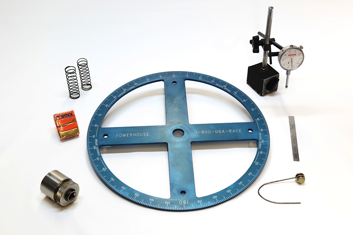
[2]Shown are the main tools needed to check piston-to-valve clearance: modeling clay, machinists scale, dial-indicator and base, timing wheel, pointer and checker springs. (Photos: Ed Taylor)
 [3]
[3]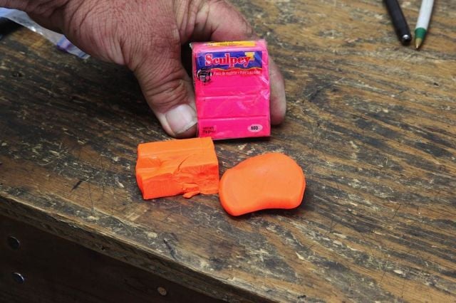 [4]
[4]
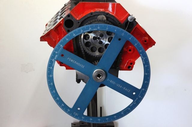
The short block is set up with the camshaft, timing set, crankshaft and at least the Number 1 piston and connecting rod with the proper bearings. Make sure the cam is degreed for the intended setup as the cam position will affect piston-to-valve clearance. The valves are installed on the cylinder head for the corresponding cylinder using checking springs (more on those later). The clay method doesn’t require a timing wheel, but we’re setting up in preparation for demonstrating the dial-indicator method. A simple crank socket and ratchet can be used in place of the wheel for turning the engine over while using the clay method. After attaching the timing wheel and pointer, set true top dead center (TDC). Modeling clay can be purchased at a local craft store. This is non-hardening clay that molds very easy when it's warm.
 [5]
[5]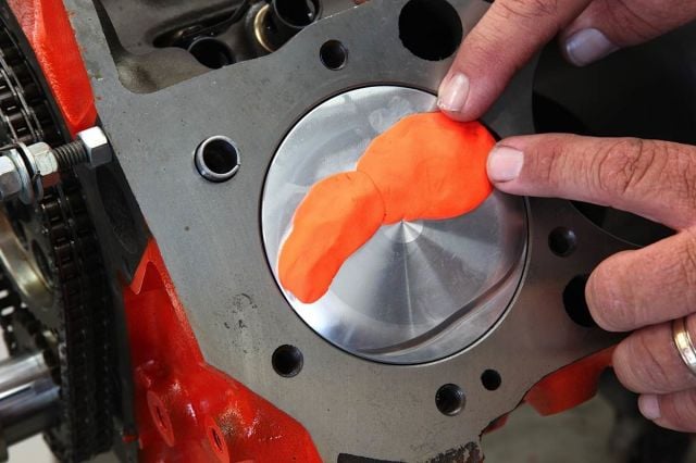 [6]
[6]
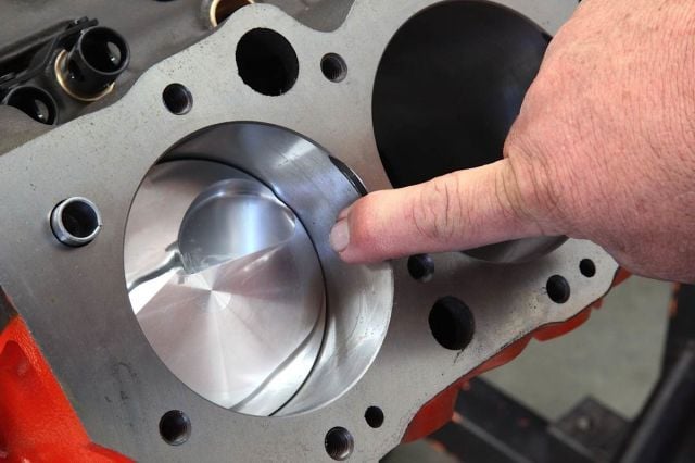
Before placing clay on the piston, apply a thin coating of either WD-40 or light engine oil on the cylinder wall to help keep the clay from sticking during the measurement process. Press a generous piece of clay into the two valve reliefs on top of the piston. Avoid excessive amounts of clay on the edge of the piston to keep clay off the cylinder wall during measurement.
 [7]
[7]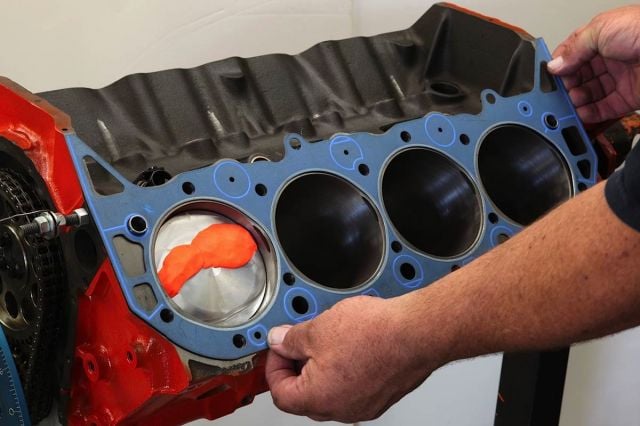 [8]
[8]
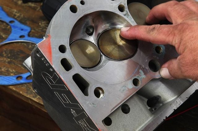
Each valve receives a light oil treatment to help keep the clay from sticking to the valve face as the crankshaft is rotated. A head gasket with the proper thickness is required to ensure accurate clearance measurements. We used a pre-flattened gasket. Otherwise, you’ll need to measure the thickness of your new gasket, then check with the manufacturer to find the compressed thickness. Once you determine the difference, you can subtract that number from your measurement, and this total should still be within .001 to .002 of the exact clearance.
So, how much clearance is enough? A safe rule of thumb is .080-inch for intake valves and .100-inch for exhaust, which requires a little more clearance because of the increased heat factor. Experts also suggest adding .030 to each valve if the engine is equipped with aluminum rods as they tend to stretch more than steel.
 [9]
[9]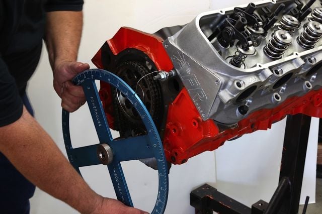 [10]
[10]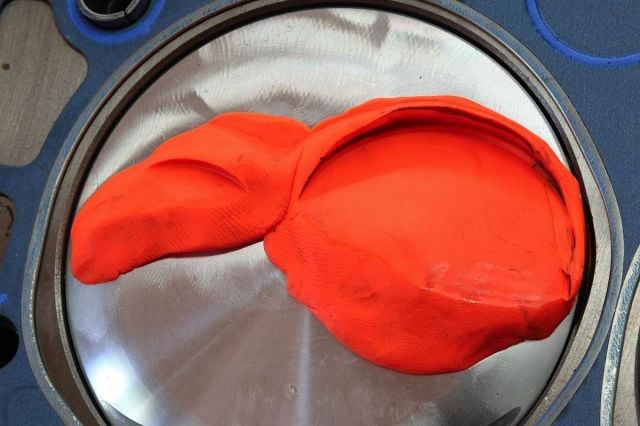 [11]
[11]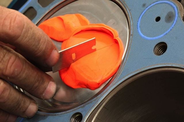 [12]
[12]
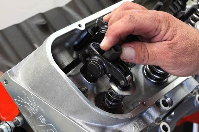
Position the cylinder head on the block and use enough head bolts to tighten snugly. Install the lifters and pushrods. If the engine is to be built with hydraulic lifters, they cannot be used for checking clearances. Hydraulic lifters will bleed down and corrupt the measurements using both the clay or indicator methods. A solid lifter must be used for measurments. Install the rocker arms and zero the valve lash. Finger-tight is okay for securing the rocker arm. Note the checker springs. Regular valve springs can be used for the clay method, but it’s much tougher to rotate the crank. With a ratchet and crank socket--or in our case, the timing wheel--rotate the crankshaft in the normal direction several times to ensure that the valves make a good clean impression in the clay. Remember, it takes two crankshaft rotations to completely rotate the camshaft once. There’s a chance the clay may adhere to a valve, so carefully remove the cylinder head so that the clay is not disturbed. Now you can observe the distinct impressions in the clay on top of the piston. Use a razor blade or thin, sharp knife to cut carefully through the center of the impression made by the intake valve.
Any number of factors or changes to an engine will influence piston-to-valve clearance, such as decreasing the piston deck height or angle milling the cylinder heads–both of which will boost the compression ratio but require disassembling the engine and machine work. More prevalent, however, is swapping in a more aggressive camshaft or increasing the rocker-arm ratio. Both changes are much easier to facilitate and will increase valve lift and shift the timing of when the piston and valve enter close quarters.
Advancing or retarding the camshaft will also affect P2V clearance. Advancing the cam helps build low-end torque but it also decreases the intake P2V clearance while increasing exhaust clearance. It’s the just the opposite for retarding cam timing when higher RPM power is desired–increased intake P2V clearance with decreased exhaust clearance.
 [13]
[13]
undefined
Fear of Flycutting
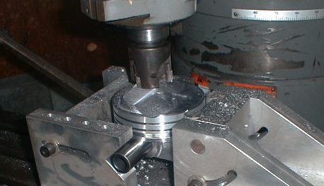
What if piston-to-valve clearance is too tight? The valve-relief pockets in the pistons will have to be flycut by an experienced machine shop. The following tips will be helpful:
- If possible, mark the valve center on the piston with a center punch. Many engine builders cut the head of an old valve and turn down the stem to a sharp point for a makeshift punch that fits into the guide.
- Inform the machine shop of the cylinder head, valve angle, valve size and whether or not the head has been angle milled.
- Mark the cylinder number for each piston because some engines have alternating intake-exhaust arrangement.
Clay or dial indicator?
The two most popular methods of checking P2V clearances are clay and dial indicator. Clay is an economical choice for street and homebuilt engines while the dial indicator is preferred by many pros in high-horsepower applications. These methods cover 99 percent of the performance and racing market, but there is a group of engines built with extremely close tolerances that demand very sophisticated and sometimes proprietary measurement methods. These builders have access to advanced computer modeling software and laser scanning to ensure accuracy. It’s a completely different atmosphere in these engine shops, and someday these techniques and equipment will filter down. For now, however, the clay and dial-indicator methods are the preferred choices by most engine shops.
The clay method involves applying a small quantity of clay on the top of the piston, installing the cylinder head and rotating the crankshaft so that both valves cycle through a simulated firing. The head is removed and the impressions that the valves left are measured. Using the a dial indicator method, the engine builder uses a more precise measuring instrument and can observe the actual clearance from the point where P2V interference is likely to occur.
The clay method doesn’t require special tools, only a slice of children’s modeling clay from any arts and crafts store and an accurate ruler. The dial-indicator method requires a dial indicator, mounting base and a degree wheel.
There is debate as to the accuracy of the clay method. Different factors can affect the outcome, such as clay density, whether or not the clay remained compressed and whether the valves pulled on the clay impression. Also, the exact area of minimum clearance may not be obvious. However, the clay method does provide some insight into the valve’s radial clearance.
What is radial clearance?
Radial clearance is the distance from the edge of the valve to the valve-relief pocket in the piston. The piston will rock slightly when at top-dead-center, which could bump into the valve edge. There are also high-horsepower applications such as Pro Stock where the valve lift is more than one inch and the valve stems are extremely long to allow large ports. At full lift, the valve head is inches away from the bottom of the valve guide. At that distance, any slop between the stem and guide is magnified at the end of the valve. So, between the piston rocking and valve head flopping, the valve edge could hit the valve-relief pocket in some piston designs. Experts suggest a minimum .050-.060 inch radial clearance.
 [14]
[14]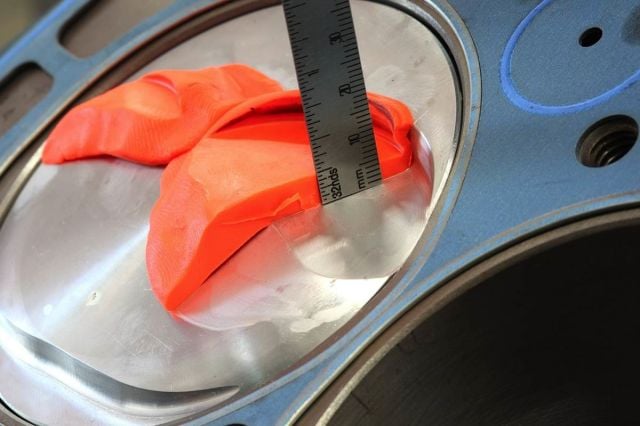 [15]
[15]
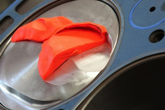
Carefully lift away the outer half of the clay to reveal the clearance between the piston and valve. Use a machinist’s scale or the depth probe on a dial caliper to get an accurate measurement of piston to valve clearance at the thinnest area of the clay impression.
 [16]
[16]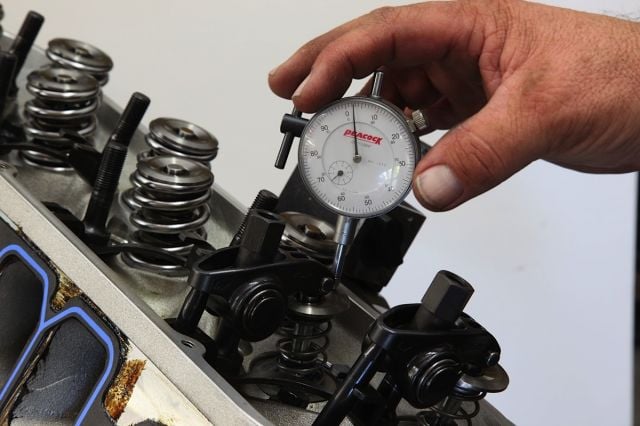 [17]
[17]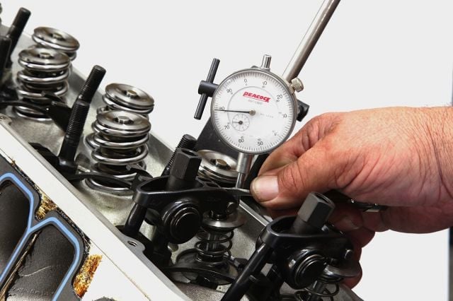 [18]
[18]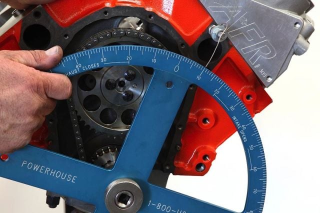 [19]
[19]
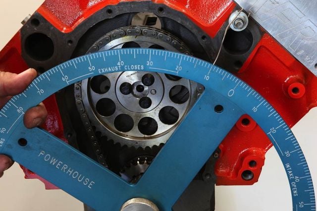
For the dial indicator method, follow all the previous setup steps except placing clay on the piston top. Again, use solid lifters, install the rocker arms and set zero lash. Rotate the crankshaft clockwise until the degree wheel indicates the Number 1 piston is at 10 degrees ATDC on the intake stroke. This is the crank angle where interference is most likely to happen--not at TDC or at maximum intake-valve lift. At this point, the piston on its way down and, depending on the cam lobe profile, the intake valve is trying to chase it down. Mount the dial indicator on the cylinder head and position it over the retainer of Number 1 intake valve. Set the dial indicator to zero. Make sure that the plunger on the dial indicator has plenty of range to move up and down. Use a small screwdriver or pick to push tip of the rocker arm downward until you feel the valve contact the piston. Observe the dial indicator to determine the actual piston to valve clearance. To measure the clearance on the exhaust valve, rotate the motor clockwise until the timing wheel is at 10 degrees BTDC on the exhaust stroke. Again, this is the crankshaft position most likely to see P2V interference as the piston moves up and draws a bead
The clay method can give some indication of radial clearance after the impression is left, but as the clearances get smaller the accuracy of measuring such a small amount of clay is suspect. Radial clearance can be measured more accurately by locating the valve center on the piston with a punch and using a divider to outline the actual size of the valve on the pocket.
How much clearance is enough? A safe rule of thumb is .080-inch for intake valves and .100-inch for exhaust.

Another decision facing engine builders is how many cylinders to check? If suitable clearance is found on the Number 1 cylinder, then there’s a strong chance that the remaining cylinders will be problem-free. When extremely tight clearances in high-horsepower applications are involved, then the builder may choose to check every cylinder. The old adage–measure twice and cut once–remains solid advice.