TECH5 is a regular feature where EngineLabs asks industry leaders five technical questions. This week’s guest is Dan Jesel, president and CEO of Jesel Valvetrain Innovation.
EngineLabs: What’s the highest ratio rocker arm you’ve built or heard about for a performance V8 engine? And what are the pros and cons of using a high-ratio rocker arm?
 Dan Jesel: Jesel has built rockers with ratios upwards of the 2.4:1, primarily for flat-tappet systems and in some cases because of cam lift rules, but it depends on the total motor package including the limitations imposed by the engine block and the sanctioning body rules. Jesel prefers to use larger diameter cams and larger cam lobes with lower rocker ratios. Higher rocker ratios increase the valve opening rates, but by using larger cams and lobes you can end up with similar opening rates while lowering the loads and stresses on the valve train. Cam diameters are limited by the amount of material surrounding the cam tunnel. Some cam tunnels can only be bored out to 68mm, however many NHRA Pro Stock blocks can be bored out to 82mm. Then you have the rules — some sanctioning bodies limit the cam size so in order to get more lift or loft they must use a higher ratio rocker to achieve that. There is a noticeable difference when turning over a motor with the two different packages — small cam with high ratio rocker vs. big cam lobe with lower ratio rockers. It takes more rotational force to move the high rocker ratio package, and this required force (or drag) increases with rpm. It is our experience that the large lobe/low rocker ratio package provides a smoother, more stable valve train capable of more rpm and providing better durability.
 EL: With Pro Stock engines running well over 1-inch valve lift, what are the challenges in ensuring a proper sweep pattern?
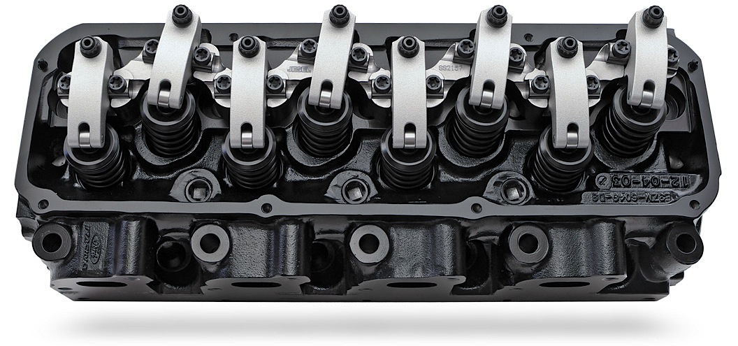
Jesel: Actually, 1-inch lift is pretty common today, Pro Stock lift is more like 1.125-inch. Everyone has their own opinion of how a rocker should sweep the top of the valve. Jesel has always set up its rocker geometry with a lowered shaft position. This will make the rocker roller sweep faster in the beginning of the lift cycle and slow down at max lift when the spring pressures are the highest. Another factor affecting the sweep pattern on the valve is the rocker’s pivot length. A longer pivot-length rocker will have less sweep on the valve. Engine builders should consider using a longer pivot rocker based on what the cylinder head will accept. The ability to relocate the rocker’s pivot point is one of the primary advantages of our shaft rocker systems. With a stud-type rocker you are relegated to a specific pivot length unless you relocate the stud, which is a total exercise in futility. An added advantage of increased rocker pivot length is less valvetrain friction and improved valve guide life.
EL: Pro Stock engine builders have said improved valve train geometry is the key to today’s engines running around 11,000 rpm. What is an ideal geometry and what are some of the tricks to achieving that goal?
Jesel: In highly loaded pushrod valvetrains like you find in Pro Stock, valvetrain deflection is your biggest enemy. Anytime the lifter is not pushing the pushrod and rocker in the shortest and straightest path you invite pushrod deflection, rocker side-thrust loads and loss of valve train control at high rpm. It is important to design a valve train as a package optimizing lifter placement, lifter bore angles, pushrod angle and rocker position. Jesel makes this possible with offset lifter bodies, offset lifter pushrod cups and offset rockers. The ideal setup is the lifter, pushrod & rocker pushing together in a straight line. Not always possible, but certainly a goal.
EL: What are some of the trends in lifter design and how is performance improved through those designs?
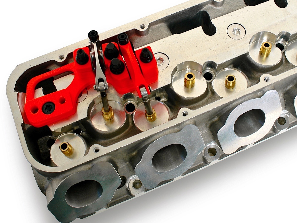
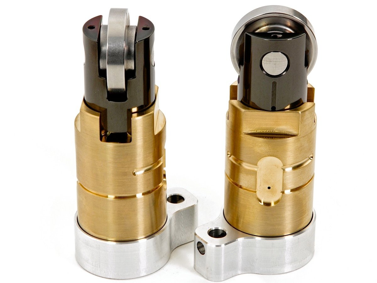 Jesel: Jesel’s R&D department is continually looking for ways to improve lifter design. We offer several different styles of roller lifters (tie-bar, dog-bone, key-way and wheel guided), because different applications require different lifters. Jesel designed the keyway-style lifter now popular in Pro Stock, but the hottest new Jesel innovation is the cartridge lifter and bushing assembly that is installed in the block through the valley and is retained with a stud or bolt. The lifter uses a large 1.220-inch diameter roller that helps reduce lifter pressure angle. Due to the added cross section between the roller’s ID and OD, the roller will be stronger, and the added diameter will help slow down the roller increasing roller durability. The large diameter roller in the cartridge lifter will allow more aggressive cam lobe profiles because of the lack of pressure angle that the lifter is seeing. Jesel’s new cartridge lifters are not for everyone because it takes a good base block that will allow you to install the large diameter bushing that is required, and you most likely will have to purchase a custom cam core with narrowed cam lobes, but the performance advantages will be well worth the effort.
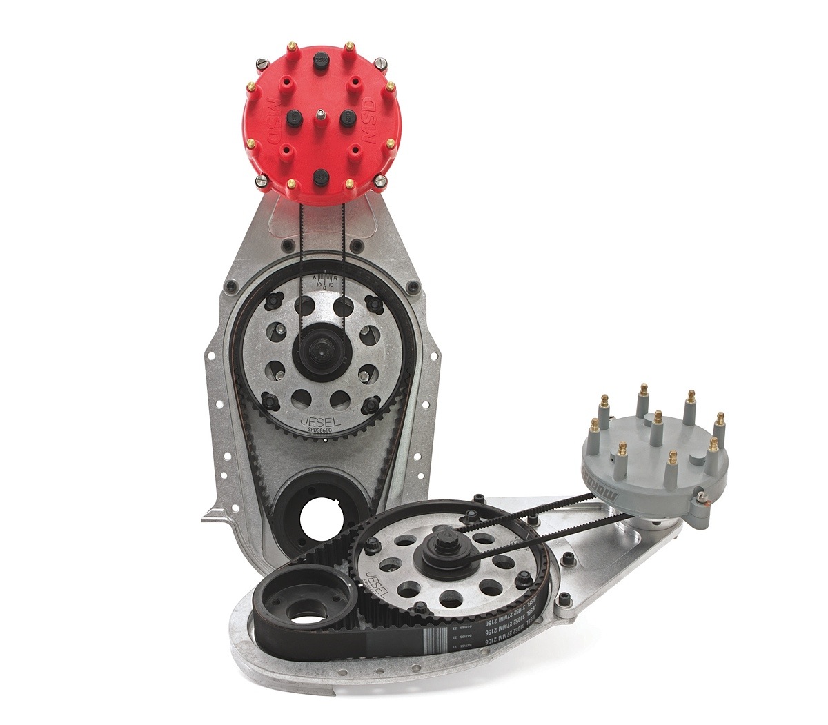 EL: What are the biggest mistakes engine builders make when installing and using belt drives?
Jesel: There aren’t too many mistakes you can make when installing a belt drive, just a few simple dos and don’ts. Probably the most important is not to crimp the belt or flip it inside out to inspect the teeth. Also, make sure you do not spray harsh chemicals (brake clean) on the belt or if the belt sees any oil you should replace it. Over time the oil will attack the belt if you don’t replace it. Make sure the belt tension is correct and doesn’t start out overly tight because the cam-to-crank center distance will grow as the engine block gets hot, making it tighter at operating temperature. Replace the belt if you think it has endured some abuse or any type of engine failure or sudden stop. These belts were not designed to last forever so after 250 runs on the drag strip, or every time the motor gets freshened (oval track or endurance racing), it is cheap insurance to change it. Some other points worth addressing is cam end-play and front cover sealing. If you run a standard bronze thrust package you need about .008-to-.012-inch camshaft endplay. We also offer needle thrust bearing cam adapters so that you can tighten up that end-play to .002-to-.005 inch to reduce lifter roller thrusting. Make sure the cam and crank seals are dry – they do not need any lubrication before assembly, and you many want to consider drilling out the dowel pin holes in the cover or removing the dowels in the block to allow the cover to center itself on the crank and cam.